
TouchBLUE tablet manual
TouchBLUE tablet manual
This is the user manual for the TouchBLUE touch-screen tablet that runs BlueCarve machines with a FluidNC controller. The same manual is built into the tablet: open the tablet’s web page from a computer on the BLUECARVE WiFi and choose Manual.
Video tutorial
A narrated walk-through of TouchBLUE 1.3.5: every screen, a first carve, and the five most common alarms.
Watch it at https://bluecarve.com.au/wp-content/uploads/2026/11/TouchBLUE-1.3.5-Tutorial.mp4
Read this first: safety
A CNC machine can cause serious injury. The TouchBLUE tablet makes the machine easy to control, but it does not make it safe by itself. Please read and follow these points every time you use the machine.
- Know where the machine’s emergency stop (E-stop) is and be able to reach it at all times while the machine is moving. The STOP button on the tablet ends a job and returns the machine to idle, but it is not an emergency stop and does not cut power.
- Never leave a running machine unattended.
- Wear eye and hearing protection and use dust extraction. Keep long hair, loose sleeves and jewellery well away from the cutter.
- Clamp the material securely before every job. Keep your hands clear of the cutter and gantry while the machine is powered.
- Check the cutter, collet and spindle before starting, and use only cutters rated for the spindle speed and the material.
- Keep children and pets away from the machine.
- If anything looks, sounds or smells wrong, press the E-stop first, then work out the cause.
The screen pictures are illustrations that follow the tablet’s layout. Machine names, file names and positions on your own tablet will differ.
1. Getting started
This section is for first-time users. It explains what TouchBLUE is, how to switch on and connect, what each screen does, and the handful of ideas you need before your first carve: homing, jogging and setting zero.
1.1 What TouchBLUE does
TouchBLUE is a touch-screen controller for your BlueCarve machine. The tablet talks to the machine’s controller over WiFi. You use it to:
- move the cutter around (jogging) and send the machine to its reference position (homing);
- tell the machine where your job starts (setting zero), by hand or with a touch probe;
- choose, preview and run job files, and watch them carve;
- pause or stop a job, and adjust speeds while it runs;
- see alarms and errors explained in plain English.
1.2 Switching on and connecting
- Switch on the machine’s own power (the controller must have power, not just a USB connection).
- Power the tablet with its USB-C power lead. The TouchBLUE logo appears, then the main screen.
- Wait for the connection. The tablet joins the machine’s WiFi network by itself. Look at the bar at the bottom of the screen: when the word at the left changes from a red OFFLINE to a green IDLE, you are connected.
- If the bar shows ALARM in red, a message explains why. Tap Clear Alarm, or see section 3.
| Preset connection details | |
|---|---|
| Machine WiFi network name | BLUECARVE |
| WiFi password | bluecarve |
| Controller address | 192.168.0.1 |
| Tablet web page (send files, Tools, this manual) | Normally http://192.168.0.2. The exact address is shown on Settings > Machine. |
1.3 Finding your way around
The row of tabs along the top is the main menu. The bar along the bottom is always visible and shows the machine state and position.
| Tab | What it is for |
|---|---|
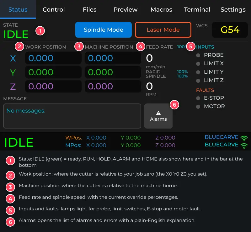
| Status | The live view: state, positions, feed and spindle speed, input and fault lamps, messages and the Alarms button. Also holds the Spindle Mode / Laser Mode buttons. While a job runs it shows Pause and STOP. |
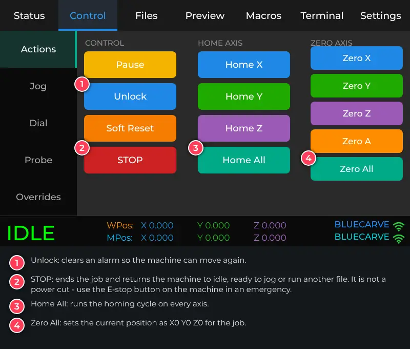
| Control | Everything for moving the machine. It has five pages down the left: Actions (unlock, home, zero), Jog (step buttons), Dial (handwheel dials), Probe (touch-probe routines) and Overrides (change speed during a job). |
| Files | The files on the machine’s SD card. Each file has a delete, preview (eye) and play button. |
| Preview | A drawing of the toolpath for the file you chose, with the job size in millimetres. |
| Macros | Buttons for saved sequences of commands. |
| Terminal | Advanced: type commands to the controller and read its replies. You do not need this for normal use. |
| Settings | Tablet settings: General, Backup, Power, Jog, Probe, WCS and Machine. |
1.4 Reading the machine state
The machine state appears in large letters at the bottom left of every screen, and on the Status tab.
| State | Colour | What it means |
|---|---|---|
| IDLE | Green | Ready. You can jog, set zero or start a job. |
| RUN | Cyan | A job is running. |
| JOG | Cyan | A jog move is in progress. |
| HOME | Blue | The homing cycle is running. |
| HOLD | Yellow | Paused. Press Resume to carry on. |
| ALARM | Red | The machine has stopped for a reason. A message explains it. Fix the cause, then clear the alarm. See section 3.4. |
| OFFLINE | Red | The tablet is not connected to the machine. See section 3.2. |
The bottom bar also shows WPos (work position, relative to your job zero) and MPos (machine position), with the machine name and WiFi network at the right.
1.5 A few words you will see
| Word | Meaning |
|---|---|
| Home / homing | Sending the machine to its limit switches so it knows where it is. Do this after every power-on, before jogging to your job. |
| Jog | Moving the machine by hand with the tablet, as opposed to running a job file. |
| Machine position (MPos) | Where the cutter is measured from the machine’s home corner. It does not change when you set zero. |
| Work position (WPos) | Where the cutter is measured from your job’s zero point. Job files use this. |
| Zero (work zero) | The point on your material that the job treats as X0 Y0 Z0. You set it each time you place new material. |
| G-code | The instructions in a job file (usually ending .nc or .gcode), produced by your CAM software. |
| Spindle / Laser mode | Which tool the machine is set to use. See section 1.9. |
| Feed rate | How fast the cutter moves through the material, in millimetres per minute. |
| Probe | A touch plate or block that lets the machine find the top (and sides) of your material automatically. |
| WCS | Work coordinate system – a stored zero point (G54 is the default). The tablet normally uses G54. |
| Spoilboard | The sacrificial board on the machine bed that you cut into slightly. Surfacing it (section 4.2) makes it flat and parallel to the cutter. |
1.6 Homing the machine
Home the machine each time you switch it on. This lets the controller know where the cutter is, which it needs to keep the cutter inside the machine’s travel limits.
- Make sure the cutter is clear of the material, clamps and anything on the bed, and that the path to the home corner is clear.
- Go to Control > Actions.
- If the state is ALARM, tap Unlock first.
- Tap Home All. The state shows HOME while the machine moves to its limit switches, then returns to IDLE.
1.7 Moving the cutter: Jog and Dial
There are two ways to move the cutter by hand. Both are on the Control tab.
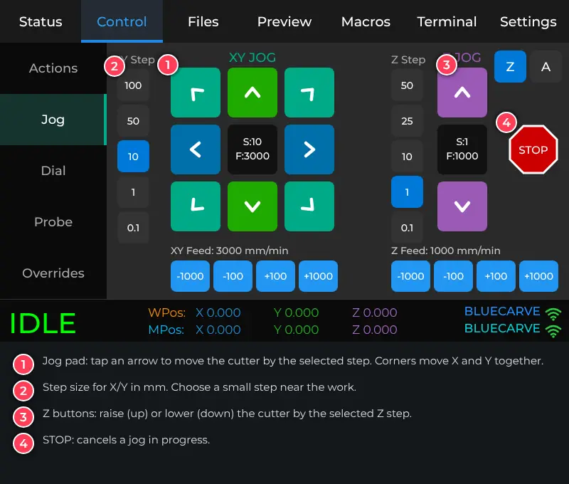
Jog: step buttons
- Open Control > Jog.
- Pick a step size from the column on the left (X/Y) or right (Z). 100 mm moves a long way; 0.1 mm is for fine adjustment.
- Tap an arrow. The cutter moves by exactly one step. The corner arrows move X and Y together.
- The S: and F: figures in the middle show the current step and feed rate. Use the −1000 / −100 / +100 / +1000 buttons to change the feed.
- Tap STOP to cancel a move that is still in progress.
Dial: handwheel-style jogging
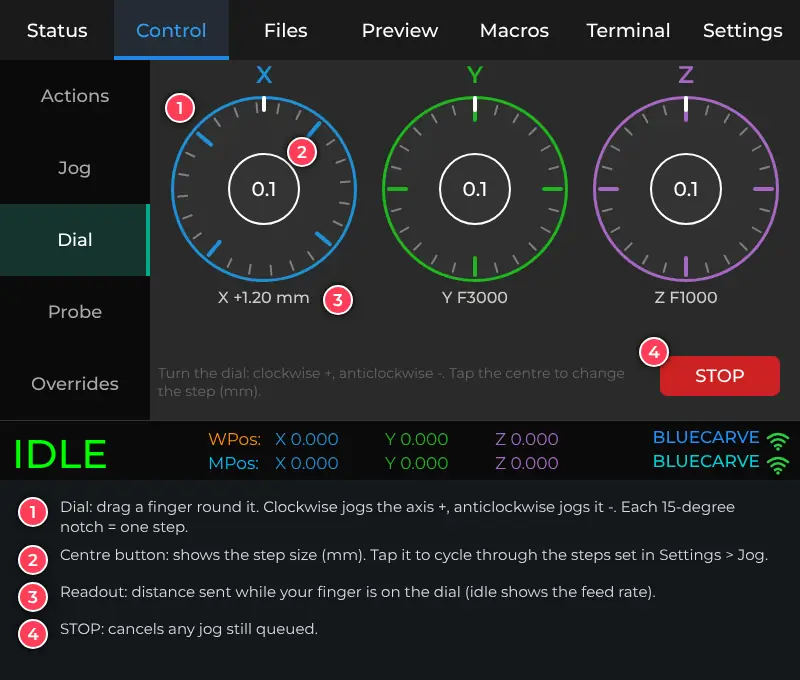
The Dial page has one dial for each axis (X, Y and Z, plus A if your machine has a rotary axis). Put a finger on a dial and turn it:
- Clockwise moves the axis in the plus direction; anticlockwise moves it in the minus direction.
- Every notch you turn (15 degrees) moves the axis by one step. Turn faster to move further.
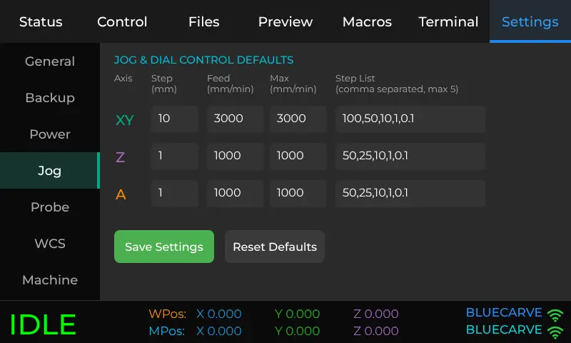
- Tap the centre of a dial to change its step size (the choices come from Settings > Jog).
- While you turn, the figure under the dial shows how far you have moved. STOP cancels any move still queued.
1.8 Setting zero (where your job starts)
Your job file measures everything from a zero point. Before each job you tell the machine where that point is on your material. The zero is set for X and Y (usually a corner or the centre of the work) and for Z (usually the top surface of the material, or the spoilboard, depending on how your CAM file was set up). Check how your file was prepared – the zero in the tablet must match the zero in your CAM software.
By hand
- Jog the cutter to the XY point that is your job’s zero (for example the front-left corner of the material).
- On Control > Actions, tap Zero X and Zero Y (or Zero All to include Z).
- Jog the cutter down until it just touches the Z reference (for example the top of the material, or a sheet of paper that just drags). Tap Zero Z.
- Check the WPos values on the Status tab: the axes you zeroed should read 0.000.
With the probe
The Probe page does the touching for you.
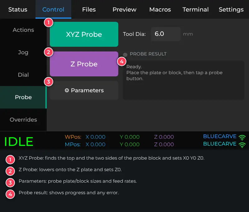
- Z Probe lowers the cutter onto the Z plate and sets Z zero. Set the plate on the material under the cutter and attach the probe clip to the cutter first.
- XYZ Probe uses the probe block to find the top and two sides of the block and sets X, Y and Z zero. Enter the cutter diameter in Tool Dia first.
- Parameters opens the probe settings (plate and block sizes and probe speeds). The factory values are a 15 mm Z plate and a 9 mm tall probe block; change them only if your probe is different.
- The Probe result box shows progress and any error.
1.9 Spindle Mode and Laser Mode
If your machine has both a spindle and a laser, the tablet needs to know which one the job is for. Use the two buttons at the top of the Status tab. The selected mode is solid; the other is an outline. The buttons are hidden while a job is running.
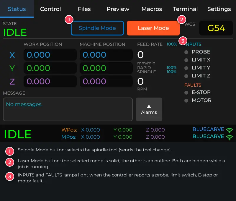
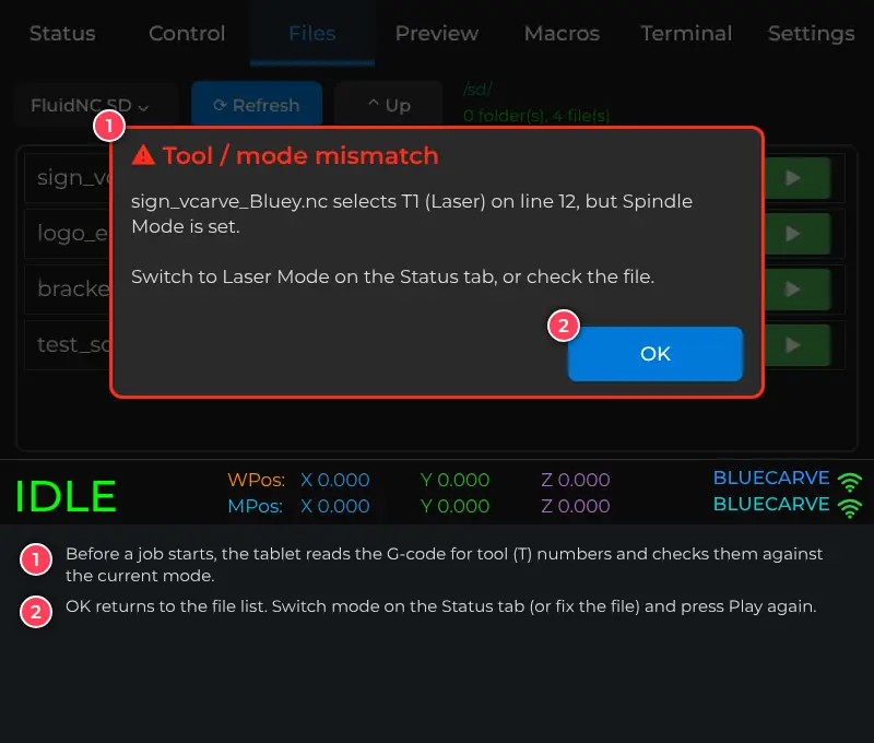
Each tool has a tool number: normally T0 for the spindle and T1 for the laser. Before a job starts, the tablet reads the file and checks its tool numbers against the mode you have selected. If they do not match it stops and tells you, which prevents (for example) a spindle job being run in laser mode.
Changing the tool numbers
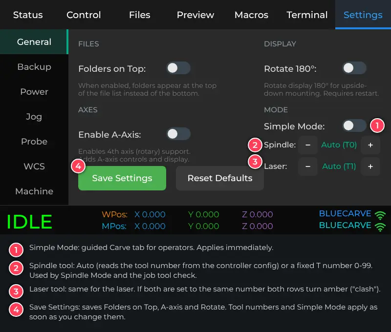
Open Settings > General. Under MODE there is a Spindle and a Laser row. Tap − or + to choose Auto (the tablet reads the number from the machine’s configuration) or a fixed tool number from T0 to T99. The change applies straight away. If both are set to the same number, both rows turn amber and read “clash” – change one of them.
1.10 Getting job files onto the machine
Job files are made in your CAM software and saved as G-code (.nc or .gcode). Make sure the file was made with the correct post-processor for your machine. A spindle job should use tool T0 (or no tool number); a laser job should use T1.
Option A: SD card
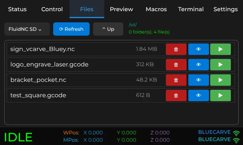
Copy the file onto the machine controller’s SD card on your computer, put the card back in the controller, and open the Files tab. Choose FluidNC SD in the list at the top left, then tap Refresh. Use a card of 32 GB or less, formatted FAT32.
Option B: WiFi from your computer
- Connect your computer (Windows, Mac or Linux) to the BLUECARVE WiFi network (password bluecarve).
- Open a web browser and go to the tablet’s address (normally http://192.168.0.2; the exact address is on Settings > Machine). The Send a file page opens.
- Drag your file onto the page, or tap to choose it. A progress bar shows the upload.
- If a job is running, or the machine is not ready, the page does not take the file and says why. Send it again when the tablet shows IDLE.
- On the tablet, open Files and tap Refresh. The new file appears in the list.
The tablet checks that the whole file arrived on the SD card. If the file name has spaces or other unusual characters they are changed to _, and the page shows the name it was saved as. If an upload is interrupted, the partial file is deleted – just send it again. If the file is refused before it is sent (for example no SD card, or not enough space), a file already on the card with the same name is kept.
1.11 Previewing a file
Before running a new file, look at it. On the Files tab tap the blue eye next to the file. The Preview tab opens and draws the toolpath. Check that the shape and size look right.
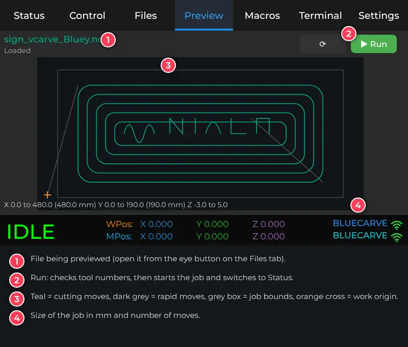
Large files take a few seconds to load; the page shows progress. If the file is very long the preview may show only the first part and the information line says so. This does not affect the job itself.
1.12 Other settings
| Page | What you can change |
|---|---|
| General | Folders on top in the file list, A-axis (rotary) on/off, rotate the display 180 degrees, Simple Mode, and the Spindle and Laser tool numbers. |
| Backup | Export the tablet’s settings to its SD card, or clear all settings. |
| Power | Screen dimming and sleep times. |
| Jog | Default jog steps and feed rates for each axis, and the step lists shown on the Jog and Dial pages. |
| Probe | Probe plate and block sizes and probe speeds. |
| WCS | Names and locks for the stored zero points (G54 to G59). |
| Machine | A summary read from the controller: axes, travel, spindle and laser, plus software versions and the tablet’s web address. |
2. Your first carve
This section takes you through a complete job from switching on to finished part. First comes the overview, so you can see the whole flow; then each step is explained.
2.1 Overview: the workflow at a glance
| # | Where | What you do | You will know it worked when |
|---|---|---|---|
| 1 | Machine + tablet | Switch on the machine, then the tablet. Wait for the connection. | The bottom bar shows green IDLE and BLUECARVE. |
| 2 | Control > Actions | Home All (clear the bed first). | The state goes HOME, then back to IDLE. |
| 3 | On the machine | Fit the cutter, clamp the material, check clearances. | The material cannot move and nothing is in the cutter’s way. |
| 4 | Status | Choose Spindle Mode (or Laser Mode). | The correct mode button is solid. |
| 5 | Files + Preview | Get the file on the machine, then preview it. | The preview shape and size are what you expect. |
| 6 | Control > Jog / Dial | Move the cutter to the start point of the job. | The cutter is exactly over your chosen X/Y zero. |
| 7 | Control > Actions | Set X and Y zero. | WPos X and Y read 0.000. |
| 8 | Control > Probe or Actions | Set Z zero (probe or by hand). | WPos Z reads 0.000 at your Z reference. |
| 9 | Files | Do the final checks, then tap Play. | The tablet checks the tool numbers and the Status tab shows RUN. |
| 10 | Status | Watch the carve. Pause, adjust or stop if needed. | The state returns to IDLE when the job is finished. |
| 11 | On the machine | Remove the part and clean up. | The machine is idle and the bed is clear. |
2.2 Step 1: Power on and check the connection
- Switch on the machine, then power the tablet.
- Wait until the bottom bar shows IDLE in green.
- If it shows ALARM, tap Clear Alarm (or Control > Actions > Unlock). If it still shows OFFLINE after about 30 seconds, go to section 3.2.
2.3 Step 2: Home the machine
Clear the bed, then go to Control > Actions and tap Home All (see section 1.6). Wait until the state returns to IDLE.
2.4 Step 3: Prepare the machine
- Fit the correct cutter and tighten the collet properly.
- Clamp the material securely. Keep clamps well away from the toolpath.
- Check that the toolpath fits on the material and inside the machine’s travel.
- Turn on dust extraction.
2.5 Step 4: Choose the mode
On the Status tab tap Spindle Mode (for a router or plasma job) or Laser Mode. The selected button turns solid. The tablet sends the change to the machine; wait a moment until the button stops looking faded.
2.6 Step 5: Choose and preview your file
- Open the Files tab. Choose FluidNC SD and tap Refresh if you have just added a file.
- Tap the eye next to your file. The Preview tab opens and draws the job.
- Check the size shown under the picture. If it is wrong, the file was probably made with the wrong units or size – fix it in your CAM software before going on.
2.7 Step 6: Move to the start point
Use Control > Jog to bring the cutter over the point that will be your job’s X/Y zero. Use big steps to get close, then the Dial page with a 0.1 mm or 1 mm step for the last adjustment.
2.8 Step 7: Set X and Y zero
On Control > Actions tap Zero X and Zero Y. On the Status tab, the work position X and Y now read 0.000.
2.9 Step 8: Set Z zero
With the probe: place the Z plate under the cutter, attach the clip, open Control > Probe and tap Z Probe. By hand: lower the cutter slowly until it just touches your Z reference and tap Zero Z. Then raise the cutter a few millimetres.
Check WPos Z on the Status tab, and that the Preview’s Z range makes sense for your job (for example, cut depths below zero).
2.10 Step 9: Final checks and Play
Before you press Play, run through this checklist:
| ✓ | Check |
|---|---|
| ☐ | Machine homed; state is IDLE. |
| ☐ | Material clamped; clamps clear of the toolpath. |
| ☐ | Correct cutter fitted; dust extraction on. |
| ☐ | Correct mode selected (Spindle or Laser). |
| ☐ | X, Y and Z zero set; the cutter is above the material. |
| ☐ | Preview checked; the job fits the material. |
| ☐ | You are standing next to the machine with the E-stop in reach. |
Then open the Files tab and tap the green Play button next to your file (or tap Run on the Preview tab). The tablet briefly shows “Checking job tool numbers…”, then starts the job and switches to the Status tab.
If you see the Tool / mode mismatch message, the job has not started. Either switch mode on the Status tab, or fix the file’s tool number in your CAM software, then press Play again.
2.11 Step 10: While the machine carves
The Status tab shows the job progress, the live positions and the speed. While a job runs the Spindle/Laser buttons are replaced by two buttons:
- Pause holds the machine; the state shows HOLD. The button changes to Resume – tap it to carry on.
- STOP ends the job. The tablet waits until the machine has come to a complete stop, then clears the alarm that a stop leaves behind, so you can jog or run another file straight away. If the machine was still moving when it was reset (ALARM 3), the tablet leaves it locked and asks you to home it – tap Home All before carrying on. If the WiFi link drops during a stop, the tablet shows Connection lost during STOP – check the machine has stopped. For an emergency, use the machine’s E-stop.
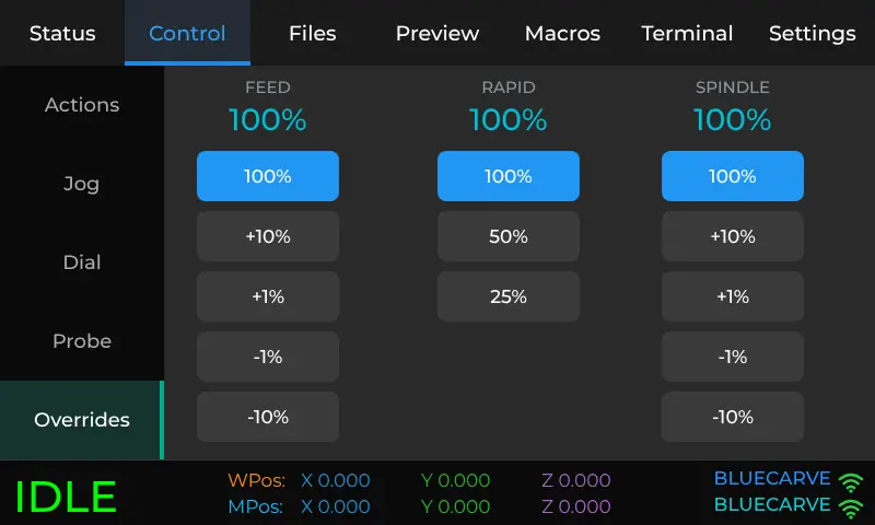
To adjust speed while the job runs, open Control > Overrides. Feed changes how fast the machine moves, Rapid changes the speed of non-cutting moves, and Spindle changes the spindle speed. 100% is the speed in the file. The tablet will not raise the spindle override if that would take the spindle above its maximum speed.
2.12 Step 11: Finish up
- When the state returns to IDLE, the job is done and the spindle has stopped.
- Raise the cutter with Z+ (or Home Z), then remove the part and clean the machine.
- To carve another copy, set zero again only if you moved the material. To carve a different file, go back to Step 5.
2.13 Doing the same with Simple Mode
With Simple Mode switched on, the Carve tab guides you through the same job one screen at a time: choose a file, fit the cutter, set X/Y zero, set Z zero, confirm, then start. The safety checks, tool check and STOP behave the same way. Switch Simple Mode on or off in Settings > General.
3. Troubleshooting
Start with section 3.1. If your problem involves an alarm message, see 3.4. The tablet shows alarms and errors in plain English, so read the message first – it usually says what to do.
3.1 First things to try
- Read the message on the screen (and tap Alarms on the Status tab to see recent alarms and errors).
- If the machine is in alarm, fix the cause, then tap Clear Alarm or Control > Actions > Unlock.
- If the tablet is acting strangely, switch the tablet off and on again (power lead out and back in).
- If the machine does not answer at all, switch the machine off and on again, wait for the tablet to show IDLE, then home.
- Make sure the machine’s own power is on. The controller needs its power supply as well as USB.
3.2 Connection problems
| Problem | What to check |
|---|---|
| The bar shows OFFLINE and does not connect | Is the machine switched on (its own power, not just USB)? Wait about 30 seconds after power-on. Restart the tablet. Make sure the tablet is within a few metres of the machine’s controller. |
| It connects, then drops out | Move the tablet closer to the controller. Metal enclosures and cabinets block WiFi. Check that no other computer is trying to take over the connection to the machine. |
| A Disconnected or Connection failed pop-up appears | Tap the connect/restart button on the pop-up. If it keeps failing, restart the machine, then the tablet. |
| The WiFi name or password was changed on the controller | The tablet is set for BLUECARVE / bluecarve. If the controller was set up with different details, contact support. |
| The web page will not open on the computer | Join the BLUECARVE WiFi first. Use the address on Settings > Machine and type it with http://, not https. Use Chrome, Edge or Firefox on a computer – the page is for computers only. |
| The web page says Files can be sent when it is Idle or A job is running | Files are only accepted while nothing is running. Wait for the job to finish (or clear the alarm), then send the file again. |
| Connection lost during STOP appears after pressing STOP | The WiFi link dropped while the machine was stopping, so the tablet cannot confirm it stopped. Look at the machine: if anything is still moving, press the E-stop. Then reconnect, check the state and home before carrying on. |
| The web page shows OFFLINE at the top right | The page can reach the tablet but the tablet is not connected to the machine. Check the machine is on and the tablet’s bottom bar shows IDLE. |
3.3 Common problems
| Problem | What to do |
|---|---|
| Jog buttons or dials do nothing | Check the state. In ALARM the machine will not move: clear the alarm first. If the state is HOLD, press Resume. If a previous move is still running, tap STOP on the Jog page. |
| The machine moves the wrong way | On the Dial page, clockwise is plus and anticlockwise is minus. If the machine moves opposite to the arrows on the Jog page, contact support (the axis direction is a machine setting). |
| Zero will not set: “Machine in ALARM”, “Still moving” or “Machine paused” | Press Unlock, wait for the movement to finish, or press Resume, then tap the zero button again. |
| Zero not set pop-up | The controller refused the command. The pop-up gives the reason; fix it and try again. Restart the machine if it keeps happening. |
| Probing fails or the probe does not trigger | Check the probe lead is plugged in and the clip is on the cutter. Make sure the clip is not touching the plate before you start, and start close enough to the plate. See alarms 4 and 5 in section 3.4. |
| Tool / mode mismatch – the job will not start | The file asks for a different tool from the selected mode. Switch mode on the Status tab, or re-post the file from your CAM software with the correct tool number (T0 for spindle, T1 for laser). |
| Tool check unavailable | The tablet could not read the file to check it (for example the SD card was busy). Wait a moment and try again, or choose Run anyway only if you are sure the mode is right. |
| Controller busy | A probe routine or mode change is still running. Wait until it finishes. |
| Mode change failed | The machine did not accept the tool change. Make sure it is idle and not in alarm, then try again. |
| Spindle limit – the spindle override will not go up | Increasing the speed by 10% would exceed the spindle’s maximum RPM, so the tablet blocked it. Lower the speed in the file if you need more room. |
| The Files list is empty or says the file system is not accessible | Check the SD card is fully inserted in the controller and the machine power is on. Use a FAT32 card of 32 GB or less. Tap Refresh. If it still fails, power the machine off and on with the card inserted. |
| A new file does not appear in Files | Tap Refresh. Check that you chose FluidNC SD at the top left, and that the file name ends in .nc or .gcode. |
| Preview is blank or slow | Large files can take several seconds. If the information line says the preview is truncated, only the first part is drawn; the job is unaffected. Tap the refresh button on the Preview tab to try again. |
| The touch screen does not respond or touches land in the wrong place | Switch the tablet off and on. Check the screen is clean and dry and that no case or screen protector is pressing on it. If it persists, contact support. |
| The screen is upside down | Settings > General > Rotate 180°, then Save Settings and restart the tablet. |
| The Spindle and Laser rows in Settings are amber and say “clash” | Both are set to the same tool number. Change one of them (usually Spindle = T0, Laser = T1). |
| After STOP the tablet says to home the machine | The machine was still moving when it was reset (ALARM 3), so its position may be lost. The tablet does not unlock it. Clear the bed, tap Home All, then set your zero again before the next job. |
| A job will not start: “file arriving”, “busy” or “not Idle” | A job cannot start while a file is being sent from the web page, while a probe or STOP is running, while another job runs, or unless the machine is IDLE. The tablet checks again at the moment the job starts. Wait, then press Play again. |
| The job stops by itself with ALARM | Read the alarm message (see section 3.4). Common causes are a limit switch hit, the E-stop pressed, or a motor driver fault. |
| Save to SD or Save & Run on the web page fails | The tablet must be connected to the machine (IDLE on the tablet) with the SD card in. “The tablet is busy” means a probe or another upload is running – wait and try again. “The machine is Alarm/Run…” means it is not idle; clear the alarm or wait for the job. |
3.4 Alarm messages
When the machine stops with an alarm, a red ALARM box appears with an explanation and a Clear Alarm button. Recent alarms are also listed under Alarms on the Status tab.
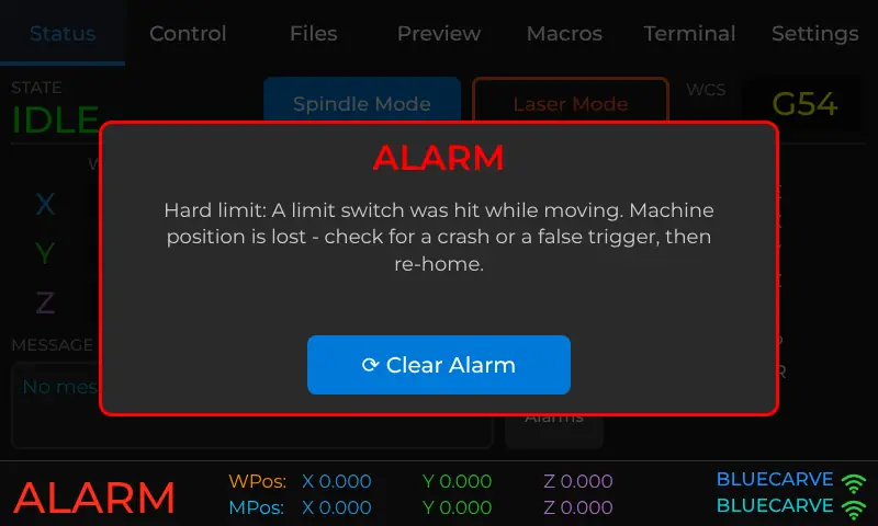
| No. | Alarm | What it means and what to do |
|---|---|---|
| 1 | Hard limit | A limit switch was hit while moving. Machine position is lost. Check for a crash or a false trigger, then re-home. |
| 2 | Soft limit | A move would go past the machine’s travel. Check the job and your work zero fit inside the bed, and home the machine so positions are correct. |
| 3 | Reset while moving | The controller was reset while the machine was still moving, so the position may be lost. The tablet’s STOP waits for the machine to stop to avoid this. If it happens, tap Home All before continuing. |
| 4 | Probe already triggered | The probe read as touching before probing started. Make sure the clip or magnet is not touching the plate and the probe lead is not shorted. |
| 5 | Probe did not touch | The probe travelled the full distance without contact. Start closer to the plate, check the clip is on the bit, or increase the seek distance. |
| 6 | Homing reset | The homing cycle was stopped before it finished. Home again. |
| 7 | Homing: door open | The safety door was opened during homing. Close it and home again. |
| 8 | Homing: pull-off failed | A limit switch was still triggered after backing off. Check the switch and wiring. |
| 9 | Homing: switch not found | A limit switch was not reached within the axis travel. Check the switch, its connector and cable, and that the axis moves freely. |
| 10 | Spindle control | The spindle or VFD did not respond as expected. Check VFD power and wiring. |
| 11 | Control input active | Usually the E-stop is pressed or a motor driver reports a fault. Release the E-stop, check the drivers, then clear the alarm. |
| 12 | Homing: switch already on | A limit switch was already triggered when homing started. Jog the axis off the switch, then home. |
| 13 | Hard stop | Motion was stopped instantly. Position may be lost, so re-home. |
| 14 | Not homed | This machine must be homed before moving. Run Home All. |
| 15 | Startup / config problem | The controller found a problem during start-up. Contact support. |
3.5 Error messages from the controller
These appear in the Alarms list or in a pop-up. The most common ones are:
| No. | Message | What to do |
|---|---|---|
| 9 | Locked by alarm or jog | G-code is blocked while the machine is in ALARM or jogging. Clear the alarm or wait for the jog to finish. |
| 15 | Jog past travel | The jog would go past the machine limits and was ignored. Jog in the other direction, or re-home. |
| 20 | Unsupported G-code | The job contains a command the controller does not support. Re-post the file with the correct post-processor. |
| 22 | Feed rate not set | A cutting move has no F feed rate. Check the post-processor, or add an F value. |
| 60–67 | SD card errors | The card could not be mounted, read or opened, or is busy. Re-seat the card, make sure the machine power is on, and do not remove the card while a job is running. |
| 65 | File not found | The file is no longer on the card. Refresh the Files list. |
| 152 | Config invalid | The controller’s configuration file has a problem. Contact support. |
3.6 Updating the software
Updates for the tablet are published on the TouchBLUE Updater web page: https://touchblue.pages.dev (it shows the latest version and has this manual to download). This updates the tablet only. Do not try to change the machine controller’s software yourself; if you think the controller needs an update, contact support.
- Use a computer with Google Chrome or Microsoft Edge and a good-quality USB data cable (not a charge-only cable). Plug the cable directly into the computer, not a USB hub.
- Open the installer page and click Install TouchBLUE, then choose the tablet’s port from the list.
- Follow the prompts. Do not unplug the cable until it says it has finished – it can take up to about 3 minutes.
- When the update finishes, switch the device off and on again.
Updating the tablet does not erase its settings.
3.7 Getting help
If you cannot solve a problem, contact BlueCarve support and have these details ready:
- the TouchBLUE version and FluidNC version (shown on Settings > Machine);
- the exact message or alarm shown, and what you were doing when it appeared;
- a photo of the screen, and of the machine if it is a hardware problem.
4. The web page: files, Tools and this manual
The tablet has its own small web page, reachable from a computer on the BLUECARVE WiFi at http://192.168.0.2 (the exact address is on Settings > Machine). Nothing needs installing and no internet is needed. It has three parts, shown across the top:
| Page | What it does |
|---|---|
| Send a file | Drop a G-code file from your computer; it goes straight to the machine’s SD card (section 1.10, Option B). |
| Tools | Surface (spoilboard surfacing), DXF → G-code (profile cuts with holding tabs), V-carve, Nest / array, Laser image, 3D relief, Viewer & checker and Feeds & speeds. Each shows the result first, then saves the job to the SD card, starts it or downloads it. The buttons under the Tools menu save and open projects. |
| Manual | This manual, stored on the tablet. |
The top right of every page shows the machine state as the tablet sees it (IDLE, RUN, ALARM, OFFLINE …). The Tools pages remember what you typed last time on that computer.
4.1 Surfacing the spoilboard
Surfacing skims the top of the spoilboard flat and parallel to the cutter’s travel. Do it when a new spoilboard is fitted, when it is scarred from earlier jobs, or whenever parts come out with uneven depth. You need a large flat-bottomed cutter (a surfacing or “fly” cutter, typically 22–50 mm).
Before you start
- Fit the surfacing cutter and remove clamps, fences and anything else from the area to be surfaced.
- Home the machine (section 1.6).
- Jog the cutter to the front-left corner of the area you want to surface and set X and Y zero there (section 1.8).
- Lower the cutter until it just touches the highest point of the board (paper test or Z probe) and set Z zero. The surfacing cut goes below this by the depth you choose.
Making the job
Open Tools > Surface on the web page and fill in the boxes. Sensible starting values are already there.
| Setting | Meaning |
|---|---|
| Width (X), Length (Y) | Size of the area, measured from the X0 Y0 corner you set. |
| Tool diameter | The surfacing cutter’s diameter, in mm. |
| Stepover | How far each row moves across, as a percentage of the diameter. 40–50% gives a smooth finish; smaller is smoother and slower. |
| Depth per pass, Passes | How deep each pass cuts and how many passes. 0.5 mm × 1 is a light skim; use 2–3 passes to take more off a badly scarred board. |
| Feed, Plunge, Spindle | Cutting speed, downward speed and spindle rpm. Use your cutter maker’s figures for MDF. |
| Safe Z | Height the cutter lifts to for rapid moves. |
| Cut along X or Y | Direction of the rows. Choose the long side. |
| Zigzag | On: cuts in both directions (fastest). Off: cuts one way only and rapids back, for a more even finish. |
| Return to X0 Y0 | Goes back to the start corner when finished. |
The Result box shows the file name, number of rows, total depth and a time estimate, and the picture shows the area and the rows. Then tap Save to SD (run it later from the Files tab), Save & Run (start now) or Download (keep the .nc file on the computer).
4.2 DXF → G-code
This turns a 2D DXF drawing (from CAD, Inkscape, LightBurn, Fusion 360, AutoCAD and most others – save as ASCII DXF, R12 or 2000) into a profile-cutting job: the cutter follows each line, circle, arc or curve in the drawing. It is meant for parts – outlines, holes, slots, signs. For lettering and logos use V-carve, and for 3D carving use 3D relief.
Steps
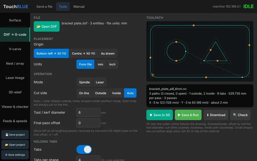
- Open Tools > DXF → G-code and click Open DXF. Choose the drawing on your computer. The page lists how many shapes it found and the drawing’s units; the toolpath appears on the right.
- If the drawing has layers, tap a layer name to leave it out (for example a dimensions layer).
- Choose where the drawing sits on the machine under Origin: Bottom-left → X0 Y0 (most common), Centre → X0 Y0, or As drawn (the drawing’s own coordinates).
- Check Units. Most drawings say which they use; if the size shown looks 25 times too big or small, switch between mm and inch.
- Choose the Mode: Spindle cuts to a depth in passes; Laser traces the lines with the laser at a set power.
- Choose the Cut side and enter the Tool diameter (see below), then the depth, speeds and safe height.
- Check the picture: the dotted outline is your drawing, the solid line is where the centre of the cutter will travel, and the white dots show where each shape starts. The box under it gives the finished size.
- Tap Save to SD, Save & Run or Download, as for surfacing.
Cut side and tool diameter
A cutter has width, so the machine must run beside the line, not on it, for the part to come out the right size. The page offsets the path by half the tool diameter:
| Cut side | Use it for |
|---|---|
| On line | The cutter centre follows the drawing exactly. Engraving, V-carving a centre line, or when your CAD already drew the cutter path. |
| Outside | Cutting a part out: the cutter runs outside the shape, so the part is the drawn size. |
| Inside | Cutting a hole or window: the cutter runs inside the shape, so the hole is the drawn size. |
| Auto | Outer shapes are cut outside and any shape drawn inside another (holes) is cut inside. Right for most parts with holes in them. |
Shapes too small for the cutter (for example a 4 mm hole with a 6 mm cutter) are skipped and the page says so. Small shapes are cut before big ones so holes are finished before the part comes free. Offset cuts run in the climb direction (outside clockwise, inside anticlockwise). Open lines that do not form a closed shape are always cut on the line.
Final pass offset
For a cleaner edge, enter a Final pass offset such as 0.3 mm. Every roughing pass then leaves that much extra material, and one more pass at full depth removes it in a single light cut. Leave it at 0 to switch this off.
Depth and passes
Total depth is how far below Z zero to cut – set Z zero on the top of the material and make the total depth the material thickness plus about 0.2–0.5 mm to cut into the spoilboard. Depth per pass sets how much each pass takes; the page works out the number of passes.
Holding tabs
Without tabs, a part comes free on the last pass and can be thrown by the cutter. Holding tabs leave small bridges of material that hold the part in the sheet; cut them afterwards with a knife or saw and sand them flush.
- Set Cut side to Outside, Inside or Auto (tabs are only used on closed shapes cut beside the line).
- Turn Tabs on. Enter Tabs per shape (for example 4), or set it to 0 and enter a spacing (for example one every 150 mm).
- Enter the Tab width (the material left along the cut, for example 5 mm) and the Tab height (how thick the bridge is, for example 2 mm). Leave Ramped edges on so the cutter rolls over each tab instead of stepping up and down.
- Check the picture: orange squares mark the tabs. The page keeps them away from sharp corners.
Passes above the tab top cut straight through; only the deeper passes lift over each tab. Shapes too small for two tabs are cut without tabs, and the result box says so – hold those with tape or screws. Tabs are also left on the final pass.
What the DXF may contain
Lines, polylines (with rounded corners), circles, arcs, ellipses, splines and blocks (grouped shapes, including nested, scaled and rotated ones) are all used. Text, dimensions, hatching and images are ignored – convert text to outlines in your drawing program if you want it cut. Lines whose ends touch are joined into one shape automatically.
4.3 V-carve
V-carving cuts lettering and logos with a V-shaped bit. The cutter goes deeper where the shape is wide and shallower where it is narrow, so letters get sharp corners and clean walls. It uses the DXF opened in DXF → G-code (with the same units, layers and origin), or open one here with Open DXF. Only closed shapes are carved, so convert text to outlines (curves) in your drawing program first.
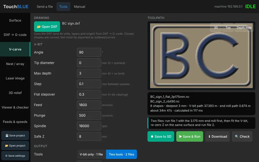
- Open Tools > V-carve and check the drawing name at the top.
- Enter the V-bit Angle (60°, 90° …) and Tip diameter (0 for a pointed bit).
- Enter a Max depth (for example 3 mm). Wide areas that would go deeper are cleared flat at this depth. 0 means no limit.
- Choose the Output: V-bit only · 1 file, or Two tools · 2 files (see below).
- Check the picture. Depth map shows the finished carving shaded; 3D and Top show the toolpath.
- Tap Save to SD, Save & Run or Download.
| Output | What happens |
|---|---|
| V-bit only · 1 file | One tool, one file. The V-bit cuts the walls and also clears any wide flat floors at max depth. Simple, but wide floors are slow and show small ridges; a smaller Flat stepover makes them smoother. |
| Two tools · 2 files | File 1 uses a flat end mill to clear the wide floors quickly. File 2 uses the V-bit for the walls and the corners the end mill can’t reach. Run file 1 first, then fit the V-bit, set Z zero on the same surface again, and run file 2. |
4.4 Nest / array
Nesting fits many copies of your parts onto one sheet, so you cut a full sheet in one job. The parts come from the DXF opened in DXF → G-code: each outer shape is one part, with its holes and any lines inside it.
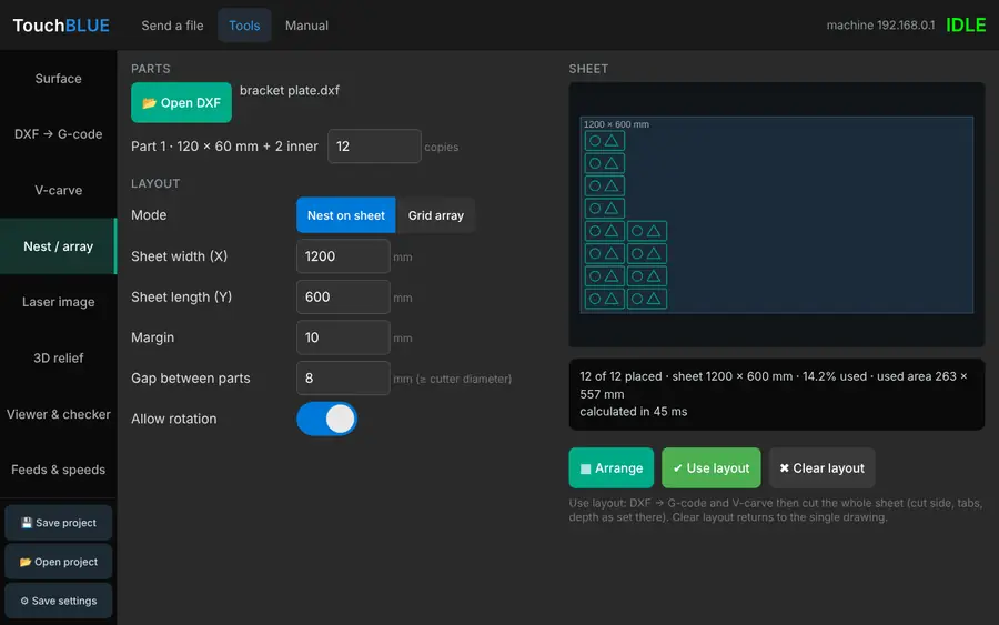
- Open Tools > Nest / array. Each part is listed with its size; enter how many copies of each you want.
- Choose Nest on sheet and enter the sheet size, the margin around the edge and the gap between parts. Make the gap at least the cutter diameter (plus a little), or the cutter will cut into the next part. Allow rotation lets parts turn to fit better.
- Or choose Grid array to repeat the whole drawing in columns and rows with a set gap.
- Tap Arrange and check the picture and the result (how many fit, and how much of the sheet is used).
- Tap Use layout. DXF → G-code and V-carve now work on the whole sheet, with the cut side, tabs and depths you set there. Clear layout goes back to the single drawing.
If not every part fits, the page says how many were left out: use a bigger sheet, a smaller gap, or cut a second sheet.
4.5 Laser image
This engraves a photo or logo with the laser, line by line, with the power following how dark each point is. Open a PNG or JPG with Open image.
| Setting | What it does |
|---|---|
| Width | The engraved width in mm; the height keeps the picture’s shape. X0 Y0 is the bottom-left corner. |
| Line interval | Distance between lines. 0.1–0.2 mm is typical; smaller is finer but slower. |
| Mode | Greyscale varies the power; Dither uses dots, good for photos on wood; Black/white cuts everything darker than the Threshold, best for logos. |
| Brightness, Contrast, Gamma | Adjust the picture before engraving. Invert engraves the light areas instead. |
| Max / Min power (S) | The laser power for black and for the lightest engraved grey. Max is usually your laser’s full power (the controller’s S range, often 1000). |
| Overscan | Extra travel at each end of a line so the laser is moving at full speed while it burns. Leave a few mm. |
The picture shows the engraving as it will burn, and the result gives the size and an estimated time. Focus the laser on the material and use the laser’s safety glasses and extraction.
4.6 3D relief
A 3D relief turns a greyscale picture (a heightmap) into a carving: white is the top surface and black is the deepest point. Heightmaps come from relief software, 3D programs or online libraries.
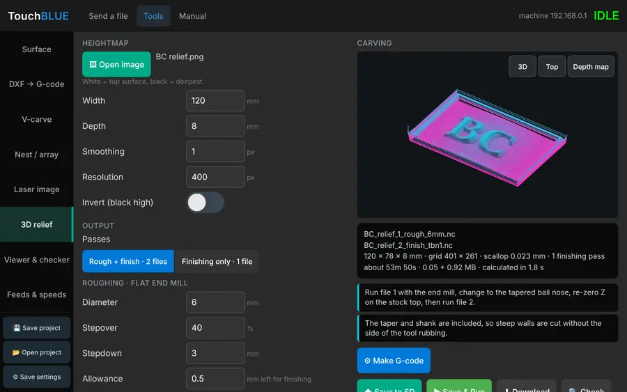
- Open Tools > 3D relief and click Open image.
- Enter the Width and the Depth of the carving. Smoothing softens a noisy picture; Resolution sets how fine the model is (higher is finer and slower to calculate).
- Choose the Passes (see below) and the finishing tool: Ball nose (enter its diameter) or Tapered ball nose (enter the tip diameter, the taper in degrees per side and the shank diameter).
- Enter the Stepover. For a ball nose 8–12% of the diameter gives a smooth finish; for a fine tapered tip 25–40% of the tip is typical.
- Tap Make G-code. Reliefs take a few seconds to calculate. Check the picture (Depth map shows the model) and the result: file names, time and the scallop height (the small ridges between passes).
- Tap Save to SD, Save & Run or Download.
| Passes | What happens |
|---|---|
| Rough + finish · 2 files | File 1: a flat end mill removes most of the material in steps, leaving a small allowance (for example 0.5 mm). File 2: the ball nose or tapered ball nose follows the surface. Run file 1, change the tool, set Z zero on the top of the stock again, run file 2. Fastest for deep reliefs. |
| Finishing only · 1 file | One tool, no tool change. The finishing tool cuts down in depth passes (Stepdown, for example 2 mm) and the last pass follows the surface. Good for shallow reliefs and fine detail. |
4.7 Viewer & checker
This shows any G-code file in 3D and checks it before it goes near the machine: open a file from the computer with Open G-code, or tap 🔍 Check under any tool to check what it just made. Drag to turn the view, shift-drag or right-drag to move it, and scroll to zoom. Cuts are coloured by depth and rapid moves are dashed; Simulate progress shows how far the job has got at any point.
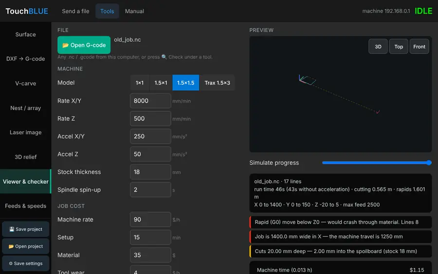
Choose your machine model and stock thickness. The checker then warns about:
- rapid (G0) moves below the material surface, which would crash the cutter;
- cutting with the spindle off, or before a feed rate is set;
- a job bigger than the machine’s travel, or cutting deep into the spoilboard;
- codes FluidNC does not support (such as cutter compensation G41/G42) and tool changes (M6).
It also works out the run time (allowing for the machine’s acceleration) and a job cost: enter your machine rate per hour, setup time, material and tool wear, the quantity and your markup to get a price.
4.8 Feeds & speeds
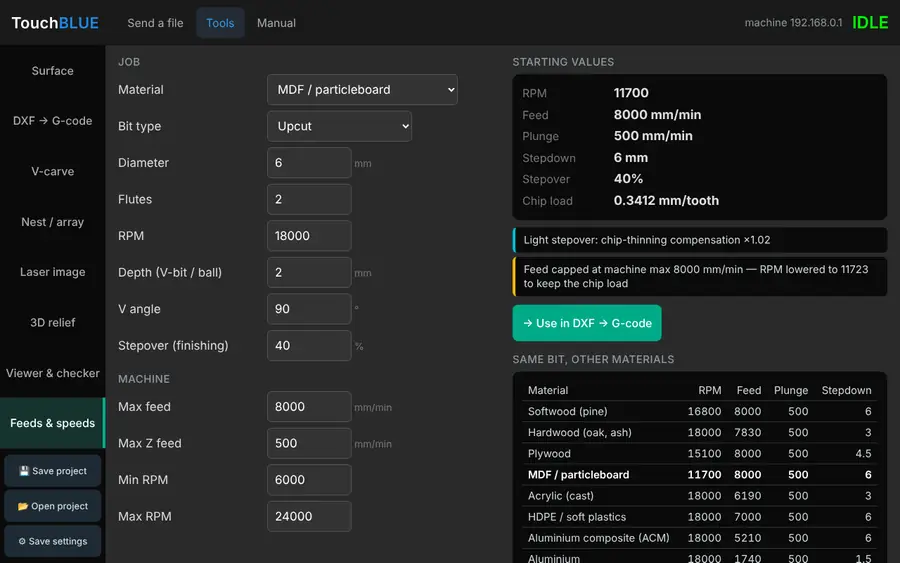
This gives starting feeds and speeds for solid-carbide router bits. Choose the material and bit type, enter the diameter, flutes and spindle speed; the page shows the RPM, feed, plunge rate, depth per pass and chip load, limited to what the machine can do (it lowers the RPM if the feed would be faster than the machine allows). The table underneath shows the same bit in other materials. Use in DXF → G-code copies the values into the DXF tool.
4.9 Saving projects and settings
The buttons at the bottom of the Tools menu save your work as a file on the computer, so you can open it again later or on another computer.
| Button | What it does |
|---|---|
| Save project | Saves every setting in every tool plus the DXF drawing, the nested layout, the laser and relief pictures and the file in the checker. Opening it puts everything back as it was, on the tool you were using. |
| Save settings | Saves only your machine, tool and cutting settings (no drawings or pictures). Use it to keep your workshop defaults, or to set up another computer the same way. |
| Open project | Opens a saved project or settings file (.touchblue). |
Files are saved to the computer’s Downloads folder (or the browser asks where to save them, if it is set to). The page also remembers your last settings in this browser, but a saved file is the safe copy.
Stuck on something? I’m Bingo. Answer a couple of questions and I’ll point you to the fix.