
Spark Plasma Legs, Table and Water Tray
Spark Plasma Legs, Table and Water Tray
These instructions cover fitting the legs (table) and the water tray, if you bought them. We make small improvements over time, so if your legs don’t match the photos in this guide, email Adam for the instructions for older models.
1. Workflow
Fully assemble your CNC before you start. Then work through these stages in order:
- Corner legs
- Middle legs (full sheet only)
- Bottom supports
- C channels (side panels)
- Install extra supports
- Insert water trays
- Join the water trays
- Connect a drain
- Insert knife slots
- Insert knives
Then turn on your CNC.
Size names used in this guide
| Short name | Machine sizes |
|---|---|
| HS | Half sheet: 1.5×1.5 only |
| FS | Full sheet: 1.5×3.0 and 1.8×3.3 |
| Landscape | 1.5×1.0 (a separate size, not HS) |
| 1.0×1.0 | 1.0×1.0 (a separate size, not HS) |
2. Tools required
Legs and table
- A helper. A second pair of hands makes this much easier.
- Tape measure
- 4mm, 5mm and 7mm hex (Allen) keys
- 8mm, 10mm and 13mm spanners
Water tray
- Drill and drill bits
- Silicone
- Plumbing fittings for your drain
3. Legs and table parts
| Size | C channels | Legs | Shorter support rails | Longer support rails | Castors |
|---|---|---|---|---|---|
| 1.8×3.3 (full sheet+) | 4 x 1320mm and 3 x 1470mm | 4 corner (full) and 4 middle (cropped) | 5 x 1575mm | 4 x 1645mm | 6 |
| 1.5×3.0 (full sheet) | 7 x 1170mm | 4 corner (full) and 4 middle (cropped) | 5 x 1340mm | 4 x 1430mm | 6 |
| 1.5×1.5 (half sheet) | 4 x 1170mm | 4 corner | 2 x 1340mm | 2 x 1430mm | 4 |
| 1.5×1.0 (landscape) | 2 x 1170mm and 2 x 910mm | 4 corner | 2 x 910mm | 2 x 1430mm | 4 |
| 1.0×1.0 | 4 x 910mm | 4 corner | 2 x 740mm | 2 x 930mm | 4 |
Each kit also includes fasteners, packed in labelled bags:
| Bag | Contents | Used for |
|---|---|---|
| A | M8 x 25mm cap head bolts, washers, nyloc nuts | Castors |
| B | M8 x 20mm cap head bolts, washers, nyloc nuts | Joining middle legs, C channels to legs |
| C | M5 x 10mm bolts, series 20 M5 drop-in nuts | Legs to the CNC rails |
| D | M6 x 12mm bolts, series 30 M6 drop-in nuts, washers, nyloc nuts | Legs to the CNC rails, bottom supports, C channels to the front rail |
| E | M6 x 16mm countersunk bolts, washers, nyloc nuts | Extra water tray supports |

4. Legs and table installation
A. Corner legs
- Prop your CNC on a table or trestles. This makes fitting the legs easier.
- Unpack each component and lay them out. Tip: group parts of the same length using the parts list.
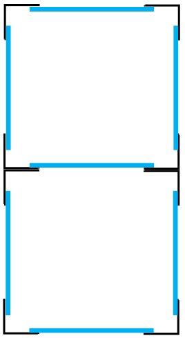
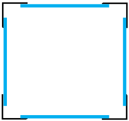
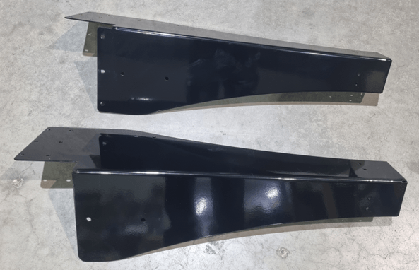
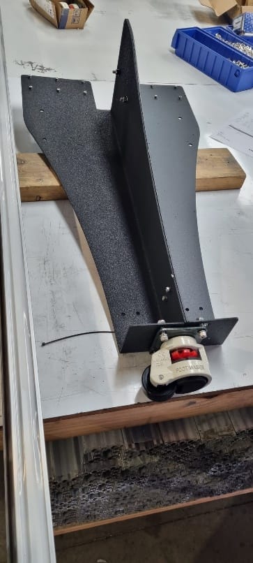
- Pick out the corner legs. HS, landscape and 1.0×1.0 tables have only 4 legs. FS tables have 8 legs: 4 with a tab and 4 without. The legs with the tab (three holes) are the corners.

The tab with three holes marks a corner leg. - Attach a castor to the bottom of each corner leg using bag A: M8 x 25mm cap head bolt, washer, washer, nyloc nut.
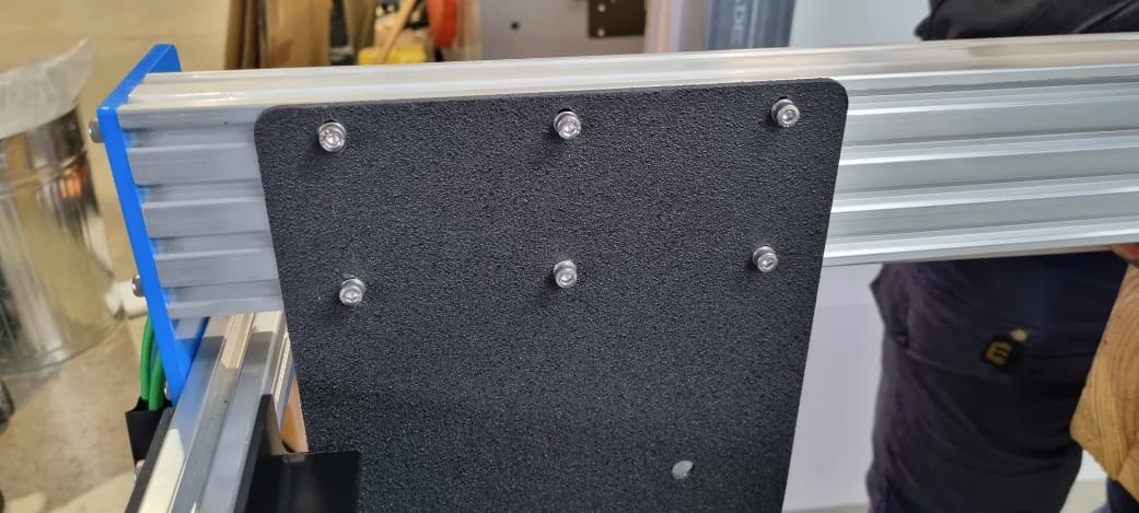
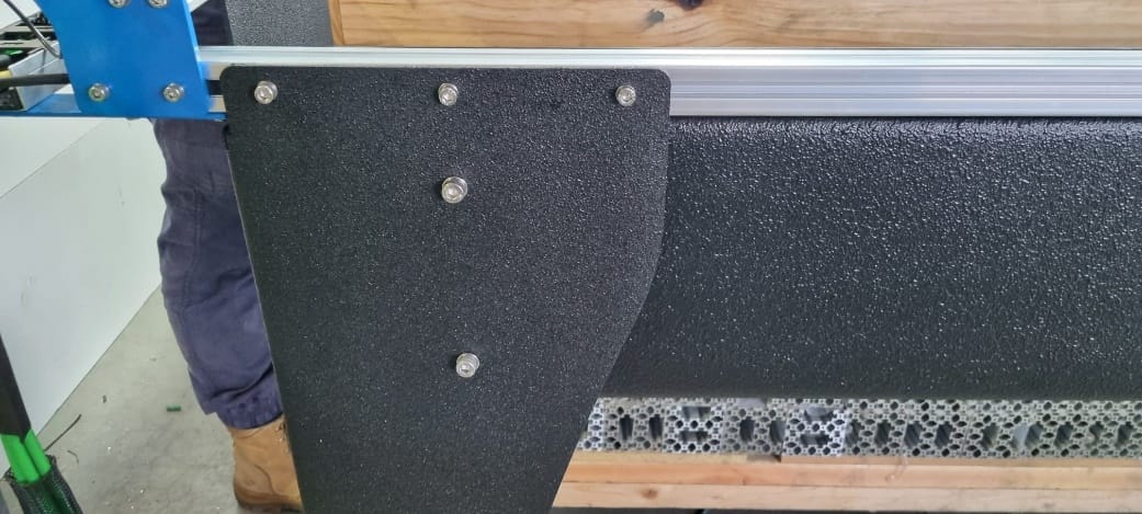
Castor fitted to a corner leg. - Loosely fit the bolts, washers and drop-in T nuts to the top of each corner leg. Drop-in nuts must drop into the V groove of the extrusion. Use bag D (M6 x 12mm bolts, series 30 M6 drop-in nuts) on the outside of the machine and bag C (M5 x 10mm bolts, series 20 M5 drop-in nuts) on the inside.
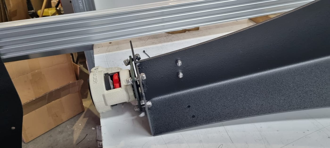
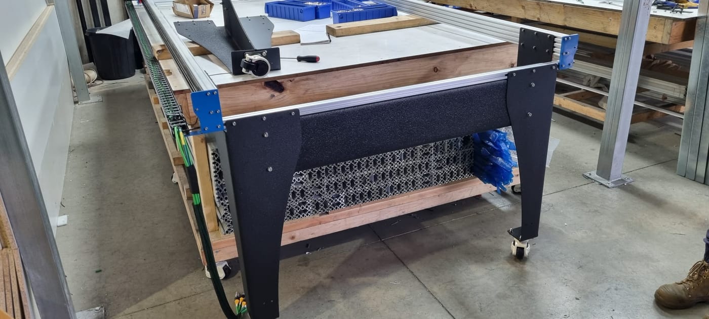
Outside of the machine. Inside of the machine. - Fit the leg to its corner. First move the leg into place and attach the outside lip to the front rail, aligning it with the top. Then line up the tall lip on the inside of the CNC rail. Tighten the bolts. Repeat for all 4 corner legs.
Corner legs fitted: attach to the front rail first, aligned to the top, then the inside.
B. Middle legs (FS only)
HS, landscape and 1.0×1.0 tables don’t have middle legs. Skip to C. Bottom supports.
- Join each pair of middle legs to make fitting easier. Use bag B for the top and bag D for the smaller bottom bolts.
Joined middle legs with castor. - Attach the castor, centred between the two legs, using bag A: M8 x 25mm cap head bolt, washer, washer, nyloc nut.
- Loosely fit the bolts and drop-in nuts to the top of the legs using bag C.
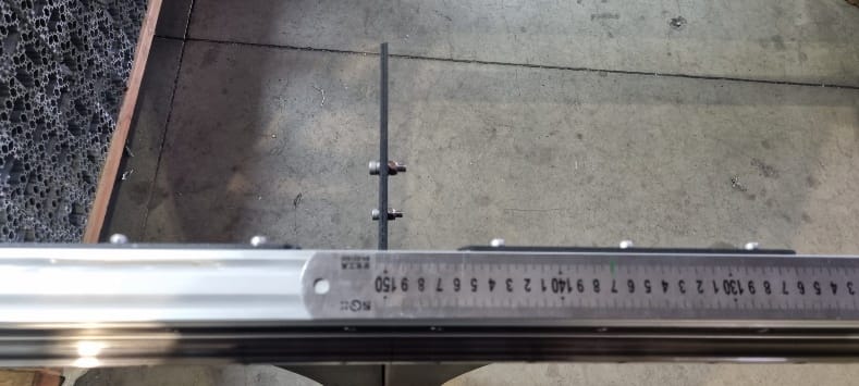
- Position the middle of the legs halfway along the extrusion. Measure from the end of the extrusion, not the end plate: 1500mm for 1.5×3.0, 1650mm for 1.8×3.3.
Measure from the end of the extrusion. - Level the legs with the top of the rail and tighten the bolts.
C. Bottom supports
Fitting the bottom supports before the C channels lets you take up any misalignment at the top. If it is out by a lot, loosen the leg bolts and adjust. Use a tape measure to check the spacing between legs is the same at the top and at the bottom. The accuracy of the legs doesn’t affect how the CNC cuts, within reason, so don’t stress about this part.
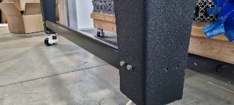
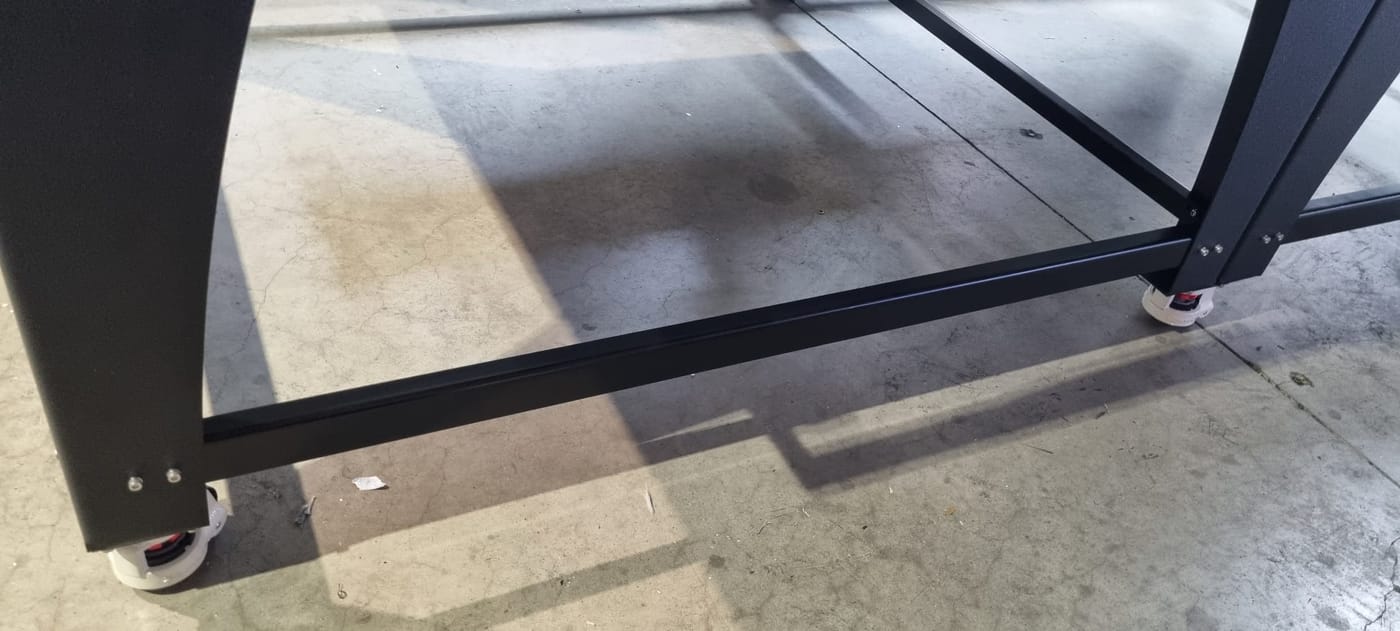
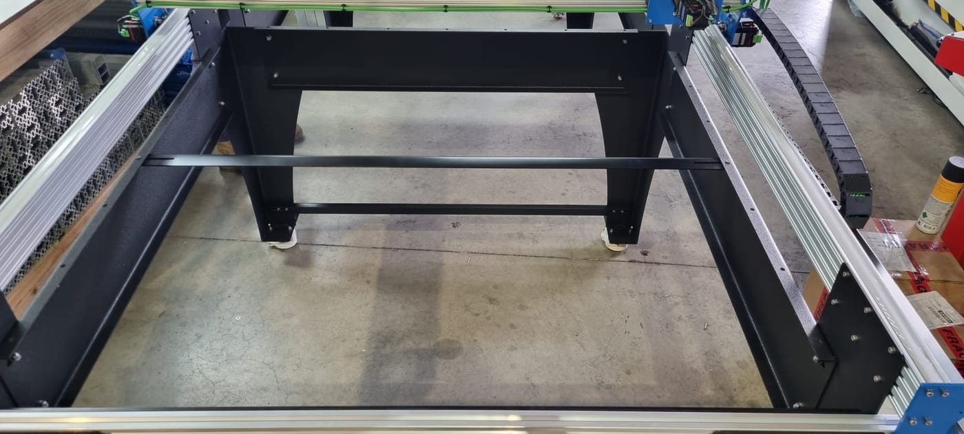
- Using bag D (M6 x 12mm bolt, washer, washer, nyloc nut), attach each support to the bottom two holes on the inside of each leg. Each size has two support lengths: the shorter rails run left to right, the longer rails run front to back. On FS tables a shorter rail also runs left to right between the middle legs.
Support rail bolted to the bottom two holes. Bottom supports fitted.
D. C channels (side panels)
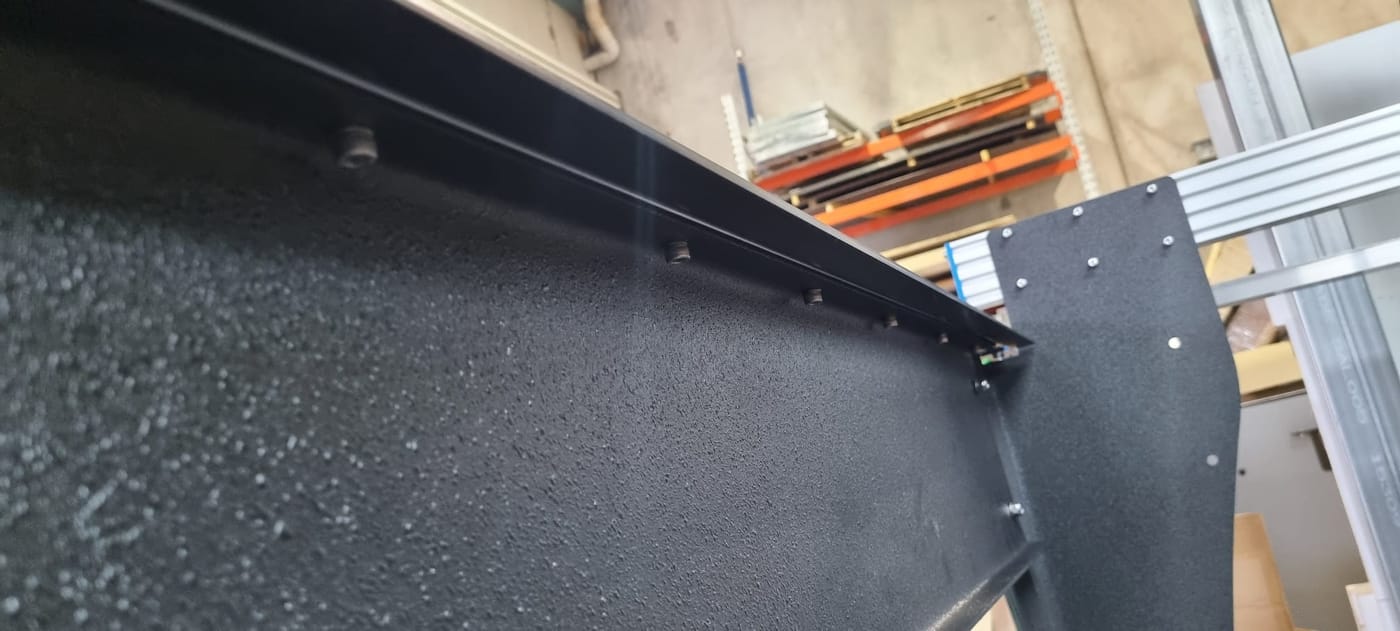
- Take a shorter C channel for the front and back. With the holes facing up, loosely fit a bolt (bag D, M6 x 12mm), washer and series 30 M6 T-nut into each hole. Fit the C channel between the front (or back) legs, sliding the T nuts up into the V slot of the rail. Attach the C channel to the legs using bag B: M8 x 20mm cap head bolt, washer, washer, nyloc nut.
Front C channel fitted up into the rail. - Take a longer C channel for each of the left and right sides. With the holes facing up, attach it to the legs using bag B: M8 x 20mm cap head bolt, washer, washer, nyloc nut.
Side C channel fitted.
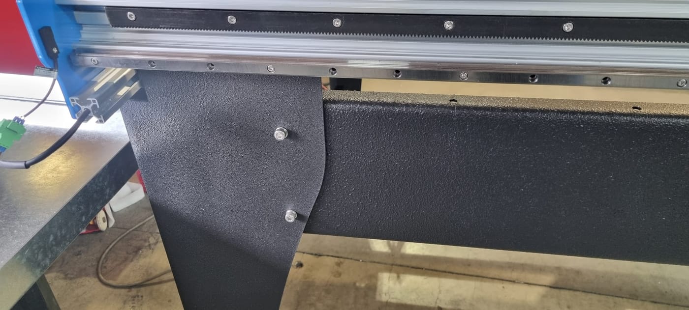
That completes the legs. If you bought the water tray, you will have one or two extra support rails. Continue to the next section.
5. Water tray installation
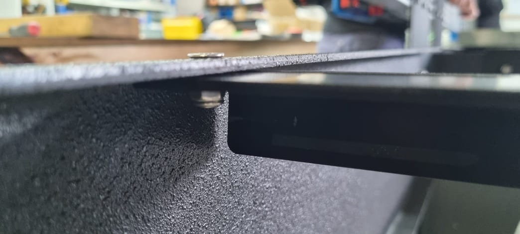
- Install the extra supports. Use shorter support rails and bag E (M6 x 16mm countersunk bolt, washer, nyloc nut). Half Sheet, Landscape and 1.0×1.0: fit 1 support halfway along. FS: fit 1 support at the first quarter and 1 at the third quarter.
Load ratingThe table is rated for a 12mm sheet of mild steel. If you plan to cut thicker material, add extra bracing to carry the weight.
Extra support across the table. Support rail fixed under the C channel. - Insert the water trays.
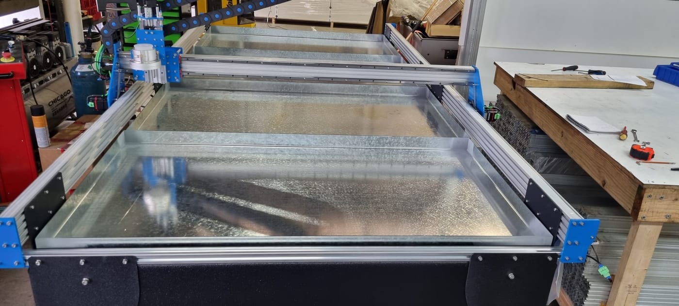
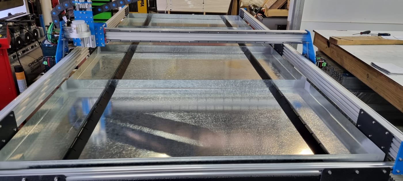
Size Trays 1.0×1.0 and landscape (1.5×1.0) 1 Half sheet (1.5×1.5) 2 1.5×3.0 3 or 4 1.8×3.3 3 Water trays in place. - Join the trays. Where one tray meets the next, rivet or bolt the trays together, with silicone between them to seal against leaks. Rivets and bolts are not included.
- Connect a drain. We don’t specify a drain method because it depends on how often you drain the system. Add plasma protector fluid to the water at 5 to 10% concentration. It stops rust on your parts and table, reduces rust flakes forming and inhibits bacteria growth.
- Insert the knife slots. Fit 2 knife slots per tray, each 200mm in from the side.
Knife slots fitted, 200mm from each side. - Insert the knives. Slot the knives into the knife supports. Each machine size uses a different number of knives.
6. Water tray safety
- Fill level. Fill the tray with water as high as possible.
- Keep water away from electrics. Keep the water, hoses and drain well away from the controller box, power supply, plasma cutter and their cables. Don’t fill or drain the tray with the electrics powered on nearby, and wipe up spills straight away.
- Disposing of the water. Water with plasma protector and cutting residue must not go down a stormwater drain. Dispose of it according to your local council and trade waste rules, and follow the disposal instructions on the plasma protector.
- Cutting aluminium. Cutting aluminium over water can release hydrogen gas, which can build up under the material and ignite. Keep the area well ventilated, and clear dross out of the trays regularly so it doesn’t build up.
7. Troubleshooting
| Problem | Check |
|---|---|
| T nuts won’t grip the rail | Drop-in nuts must drop into the V groove. Loosen the bolt, turn the nut until it sits in the groove, then tighten. |
| Legs don’t line up at the top | Fit the bottom supports first, then loosen the leg bolts and adjust. Check the spacing between legs is the same at top and bottom. |
| Middle legs in the wrong place (FS) | Measure from the end of the extrusion, not the end plate: 1500mm for 1.5×3.0, 1650mm for 1.8×3.3. |
| Table sags under heavy sheet | The table is rated for 12mm mild steel. Add extra bracing for thicker material. |
| Trays leak where they join | Seal between the trays with silicone. |
| Rust on parts or table, or smelly water | Add plasma protector at 5 to 10% concentration. |
For machine problems, see the Spark Plasma troubleshooting page.
Email adam@bluecarve.com.au with your machine model, size and a photo or short video of the problem. Owners also help each other in the BlueCarve owners group on Facebook.
Stuck on something? I’m Bingo. Answer a couple of questions and I’ll point you to the fix.