
Bluey CNC Set Up
Bluey CNC Set Up
| Version | Motors | Controller | Software |
|---|---|---|---|
| Bluey V1 | Open loop | Arduino | Easel |
| Bluey V2 | Closed loop | Arduino | Easel |
A Bluey V2 can be upgraded: see the conversion to FluidNC controller and TouchBLUE tablet.
1. Safety
Operating a CNC is relatively safe, but you must follow the precautions below. Read the full safe operating procedures before you start:
- Never leave the CNC unattended.
- Wear safety glasses and earmuffs.
- Keep your body a safe distance from the CNC.
- Keep air flowing freely to the CNC controller.
- Take care when handling router bits. They are sharp.
- Make sure everyone nearby wears suitable laser goggles whenever power is connected to the laser module.
- Restrict access to the room where the laser is operating.
- Only connect power to the laser module once it is attached to the Z axis with the lens facing down towards the waste board.
2. Unpacking and tools
What’s in the box
Inside the boxes you will find (unpacking video, 0:54):
| Item | Qty |
|---|---|
| Z and X carriage | 1 |
| M5 × 20 mm screws with washers | 8 |
| Y axis, left-hand assembly | 1 |
| X axis rail | 1 |
| Y axis, right-hand assembly | 1 |
| Rails with no brackets attached: 958 mm (1458 mm for the 1.5 m version) | 3 |
| 1000 mm rails with brackets attached | 2 |
| CNC controller box | 1 |
| USB cable | 1 |
| 24 V power supply | 1 |
| Pack of router bits | 1 |
If you ordered upgrades, you may also have received:
- Laser, attached to its mount
- Z probe
Tools you will need
- 8 mm spanner
- 10 mm spanner (to adjust the wheels after assembly)
- 4 mm Allen key or hex driver
- Phillips screwdriver
3. Assembly and wiring
Follow the videos in order. Each one shows a single stage of the build.
- Base assembly (video, 0:51)
- Y axis assembly (video, 1:40)
- X axis assembly (video, 2:48)
- Axis and limit switch wiring (video, 3:06). The wiring looms have changed since the video was made. Use the wire order in the table below.
- Belt tensioning (video, 2:49)
- Controller connection and trimmer (video, 2:38)
Axis wire order (new looms)
| Connection | Wire order |
|---|---|
| Y axis (right-hand side) | Brown, White, Blue, Black |
| X axis (left-hand side of the connector) | Brown, White, Blue, Black |
| Z axis (right-hand side of the connector) | Brown, White, Blue, Black |
Read the wire order left to right across the terminals. X and Z share one connector, as shown in the table. The left-hand Y motor is already connected at the factory.
Limit switches
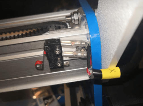
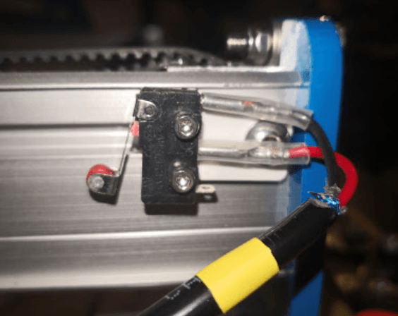
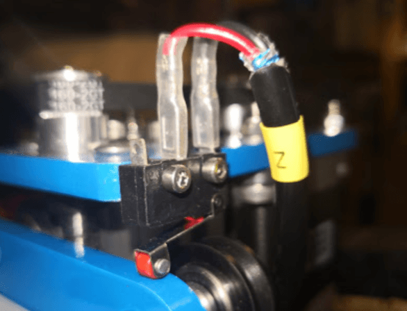
Each limit switch has a red and a black wire. The red wire always goes to the middle pin.
On every limit switch, connect the black wire to the pin closest to the start (hinge) of the switch arm, which is the pin furthest from the red roller. If you bought the Z upgrade, the Z limit switch is on the left-hand side.
4. Table, base board and waste board
Table
Set your CNC up on a solid table. How rigid the table is will decide whether your waste board stays level through the seasons, because humidity and moisture can warp a timber table and waste board. Options include:
- Steel frame with a form ply or MDF top
- Timber frame with a form ply or MDF top
The table needs to be at least 200 mm larger than your CNC’s rail size along the X axis. Minimum table sizes:
| Bluey size | Minimum table size |
|---|---|
| 1 × 1 | 1000 × 1200 mm |
| 1 × 1.5 | 1000 × 1700 mm |
| 1.5 × 1.5 | 1500 × 1700 mm |
If you make the table an extra 300 mm wider on the left of the CNC, the controller box can sit on the table. Otherwise, mount the controller box on the side of the table or under the top. Leave plenty of ventilation for the fan and air intake grille, and don’t position the controller box with the fan or intake facing up. This stops dust getting into the controller.
Base board
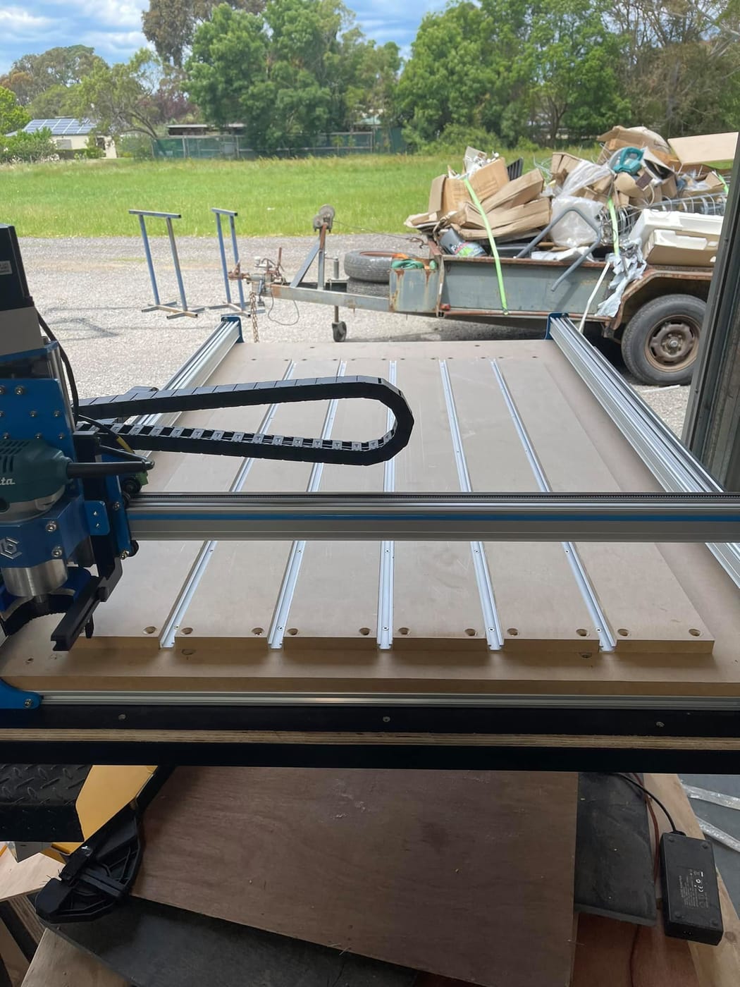
Once the CNC is on the table, install a base board. The most common materials are 18 mm (or thicker) MDF or 17 mm form ply. Form ply resists warping over time and is strongly recommended. Base board sizes:
| Bluey size | Base board size |
|---|---|
| 1 × 1 | 940 × 995 mm |
| 1 × 1.5 | 940 × 1495 mm |
| 1.5 × 1.5 | 1440 × 1495 mm |
For a 1.5 × 1.5 you may need to join two sheets.
Countersink the base board to the table using screws at least 60 mm long. The aluminium base is sandwiched between the base board and the table. Put the screws around the edges, missing the aluminium base, and avoid the middle. Screwing into the middle can pull the board down and leave a dip. You can screw down the middle if you support it with 20 mm spacers.
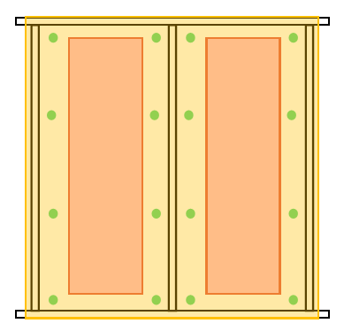
If you bought aluminium rails, install the base board the same way.
Waste board
The base board fixes your CNC to the table and adds rigidity. The waste board (also called a sacrificial board) is what you clamp your material to and cut into. It saves you replacing the whole base once it has been carved into and pitted with screw holes, so don’t be afraid to wreck it.
For a standard Bluey, use 18 mm MDF cut to the sizes below. These are maximum sizes: a larger board leaves a step between the surfaced area and the rest of the board when you surface it.
| Bluey size | Maximum waste board size |
|---|---|
| 1 × 1 | 750 × 750 mm |
| 1 × 1.5 | 750 × 1250 mm |
| 1.5 × 1.5 | 1250 × 1250 mm |
- Move the router to the bottom left-hand corner.
- Position the bottom left-hand corner of the waste board directly under the router bit tip.
- Countersink chipboard screws about halfway into the MDF. Keeping the screw heads well below the surface means the bit won’t hit them, and leaves room to surface the board later.
Aluminium rails
If you bought aluminium rails, follow Terry Brown’s rail installation guide. You still need 18 mm (or thicker) MDF between the rails. The rail height is 12 mm. Adjust the spacing between the rails to suit the number of rails you bought and your CNC size.
5. Accessories
T-slot rail clamps
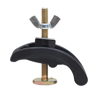

Once assembled, the clamps look like the photo above. They can be fitted anywhere along the rail. They look odd going in, but they are designed to be twisted into the slot and held by the rail walls.
Dust boot
Dust boots are not included. You can buy one from the Adam’s Bits store.
Z probe
The Z probe sets the height of your material just before you start a carve.
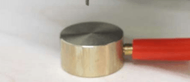

The probe is a 15 mm high aluminium puck with a red banana plug lead and a black alligator clip.
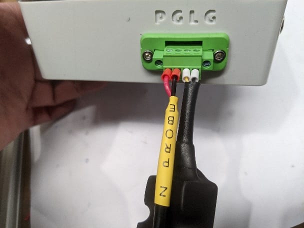
- Connect the probe wires to the controller box. The plug is labelled either PGLG or with a coloured label. Put the red wire under P and the black wire under G. If your probe has to share the laser’s green 4-pin plug, wire it into that plug the same way, then push the plug into the controller box.
- Set up probing in Easel (see Software).
- Before each carve, attach the alligator clip to the router bit and place the puck under the bit to probe.
- Remove the clip from the bit and move the puck away before you start carving.
6. Laser set-up
The laser comes with a green 4-pin plug that goes straight into the controller box, in the same PGLG socket used by the Z probe.
- Push the green plug into the PGLG socket on the controller box.
- If the laser wires have come out of the plug, reconnect them: laser positive (yellow) under L and laser negative (black) under G.
- Only connect power to the laser once it is mounted on the Z axis with the lens facing down. Everyone in the room must wear laser goggles.
Use LightBurn to run the laser. Follow the BluLaser set-up guide.
7. Spindle and VFD set-up
- The e-stop does not stop the spindle. The VFD is not connected to the controller, so always stop the spindle with the STOP/RESET button on the VFD or its power switch.
- Start the water pump before the spindle. Never run a water-cooled spindle dry.
- Any change to the motor wiring (U/V/W) or the VFD mains wiring must be done by a licensed electrician with the power isolated.
If you bought a spindle, it will be one of these:
| Power | Collet | Body diameter | Cooling |
|---|---|---|---|
| 1.5 kW | ER11 | 65 mm | Water or air |
| 2.2 kW | ER20 | 80 mm | Water or air |
Water pump (water-cooled spindles)
We supply a pond pump with a limited warranty, plus tubing with a barb fitting. If you want a spare pump, choose a submersible pond pump with a flow rate of at least 2500 L/h.
- Connect the pump to the barb on one of the two tubes.
- Put the pump in a reservoir. A large tub of more than 30 L with a lid is suggested.
- Run the other tube back into the reservoir so the water recirculates.
- Make sure the pump is fully submerged.
VFD
We use a Folinn H1 series variable frequency drive (VFD). You don’t need the manual to run it, but here are the simple manual and the detailed manual.
Your VFD comes already connected. If it has been disconnected for shipping, have a licensed electrician make the connections. Once it is connected, turn on the VFD and check that the spindle turns clockwise. If it doesn’t, turn the VFD off and let it power down completely. The electrician then swaps any two of the spindle wires on the U/V/W terminals (for example brown and black).
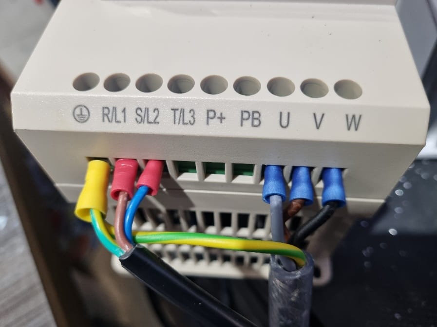
To keep things 100% reliable, we do not connect the VFD to the controller for automatic control.
Running the spindle
- Start the water pump (water-cooled spindles).
- Turn on the mains power and wait for the VFD to start up.
- Make sure the spindle and bit are clear of everything.
- Press the green RUN button.
- Turn the dial to adjust the speed.
- When the
 indicator is lit, the display shows speed. Add a zero to read RPM: 1200 means 12,000 RPM.
- Press STOP/RESET to stop the spindle.
 indicator is lit, the display shows speed. Add a zero to read RPM: 1200 means 12,000 RPM.

8. Software
We recommend Easel for the Bluey. It designs, generates toolpaths and controls your CNC in one program. Easel needs an internet connection. Set it up first by following the Easel set-up guide.
Other senders such as gSender, CNCjs and UGS will also work with the Bluey, but BlueCarve doesn’t support them.
9. Maintenance
Regular maintenance keeps your CNC accurate and enjoyable to use. The key tasks are:
- Keep the aluminium rails and wheels free of chips, dust and debris.
- Lubricate the Z axis linear rails and lead screw with white lithium grease to reduce wear and keep motion smooth.
- Check for loose bolts.
- Check for loose connections.
Cleaning
Clean the rails and wheels regularly with a brush and vacuum. While you’re cleaning, check for loose bolts and connections.
Wheels
Use a 10 mm spanner. Try turning each wheel with one finger. If it spins freely, tighten its eccentric spacer.
Belt tension
Belts can lose tension over time, which leads to sloppy carves. Home the Bluey (or move each axis to a corner by hand), then check the belt midway along its length. You should just be able to fit two fingers under it. If it is looser than that, tighten the belt at the end belt clip. To re-tension, follow the belt tensioning video.
Inspection
Things can work loose over time. Check the connections and key bolts regularly.
10. Router bits
Your Bluey comes with a starter pack of bits. You can buy more router bits and dust boots from the Adam’s Bits store.
- Use the feeds and speeds calculator to set your cutting parameters.
- The largest bit recommended for softwoods on a Bluey is 4 mm diameter.
- When cutting timber with the trimmer, set its speed dial no higher than 2½ (about 15,000 RPM).
11. Troubleshooting
| Problem | Check |
|---|---|
| Parts damaged or missing on arrival | Take photos and email them to us. Replacement parts will be sent. |
| Machine won’t home, or homes in the wrong direction | In Easel, open the Machine Inspector (Machine > Advanced > Machine Inspector, or Ctrl+Shift+D). Check that homing is on ($22=1) and the homing direction is $23=3 (Z up, X left, Y front). Type $H to home. Check the limit switch wiring: red wire on the middle pin. |
| Soft limits alarm when jogging | With soft limits on ($20=1), jogging past the travel set in $130–$132 triggers an alarm. Close the port, reopen it and home again. Check that $130 (X) and $131 (Y) match your machine’s travel. |
| USB connection drops out | Don’t sit the CNC directly on a steel table. Electrical noise can interfere with the USB connection, so fit a timber top between the CNC and the steel. |
| Sloppy or inaccurate carves | Check the belt tension, tighten any wheels that spin freely (eccentric spacer, 10 mm spanner) and check for loose bolts. |
| Dimensions slightly off | A belt-driven Bluey needs regular calibration to get within 0.1 mm. Use the MillRight calibration tool with a ruler to update your settings. |
| Step in the waste board after surfacing | The waste board is larger than the maximum size for your machine. Cut it to the size in the waste board table. |
| Dip in the middle of the base board | Screws in the middle have pulled the board down. Remove them, or support the middle with 20 mm spacers. |
| Waste board not staying level | Use a rigid table and a form ply base board, which resists warping from humidity and moisture. |
| Z probe doesn’t trigger | Check that the red wire is under P and the black under G, the clip is on the bit, and the puck is directly under the bit. |
| Bit gouges the work after probing | Make sure the clip and puck were removed before the carve started. |
| Laser doesn’t fire | Check that the green plug is fully in the PGLG socket and the laser wires are under L (positive, yellow) and G (negative, black). |
| Spindle turns anticlockwise | Power off and let the VFD fully power down. Have a licensed electrician swap any two of the U/V/W wires. |
| Spindle keeps running after the e-stop is pressed | This is expected. The VFD isn’t connected to the controller. Stop the spindle with STOP/RESET on the VFD or its power switch. |
| Dust inside the controller | Don’t mount the controller box with the fan or air intake facing up, and keep the vents clear. |
| Trimmer doesn’t fit the mount | The mount is 65 mm and fits the Makita RT0700CX. Trimmers with a larger body, such as the DeWalt (68.5 mm), won’t fit. |
Email adam@bluecarve.com.au with your machine model, size and a photo or short video of the problem. Owners also help each other in the BlueCarve owners group on Facebook.
Stuck on something? I’m Bingo. Answer a couple of questions and I’ll point you to the fix.