
Trax CNC Set Up
Trax CNC Set Up
| Version | Motors | Controller | Software |
|---|---|---|---|
| Trax, open loop | Open loop | Arduino | Easel |
| Trax, closed loop | Closed loop | Arduino | Easel |
| Trax, FluidNC | Closed loop | FluidNC | TouchBLUE tablet |
A FluidNC controller has a FluidNC sticker on the black controller box. Use the TouchBLUE manual for it; this guide’s Easel steps are for Arduino controllers. Closed-loop machines with an Arduino controller can be upgraded: see the conversion to FluidNC controller and TouchBLUE tablet.
1. Safety
Operating a CNC machine is relatively safe, but you must follow these precautions. Read the full safe operating procedures before you start: CNC router safe operating procedure and laser safe operating procedure.
- Never leave the CNC unattended.
- Wear safety glasses and ear protection.
- Keep all body parts well clear of the CNC.
- Take care when handling router bits. They are sharp.
- Keep the controller in the open with free-flowing air. Don’t put it in an enclosed space.
- Make sure everyone in the room wears laser goggles rated OD5 or higher at 445 nm (EN 207 or equivalent) whenever power is connected to the laser module.
- Restrict access to the room where the laser is operating.
- Only connect power to the laser module once it is attached to the Z axis with the lens facing down at the waste board.
- Remove the laser from the Z axis before routing.
2. Warranty
Our goods come with guarantees that cannot be excluded under the Australian Consumer Law. You are entitled to a replacement or refund for a major failure and compensation for any other reasonably foreseeable loss or damage. You are also entitled to have the goods repaired or replaced if the goods fail to be of acceptable quality and the failure does not amount to a major failure.
Operation and care
We want you to be satisfied with your new BlueCarve Trax CNC. Please read this set-up guide and follow the recommended procedures. If you have any questions about keeping your machine in good working order, contact BlueCarve CNC.
Warranty period
The warranty starts when your Trax leaves the factory (or is picked up) and runs for 12 months. It covers repairs to correct defects in materials or workmanship that existed at the time of purchase. BlueCarve CNC must approve all requests before any warranty work is done. Exceptions are listed under Exclusions. Warranty work is carried out in line with the terms, limitations and conditions below.
Limit of warranty
This warranty is only provided in Australia and to the original purchaser. By accepting the quote from BlueCarve CNC, you have agreed to help BlueCarve CNC diagnose and repair your machine. Once the problem and remedy are found, BlueCarve CNC may send you the replacement part at its cost. If a component has to be returned to the manufacturer, BlueCarve CNC will not cover the postage. BlueCarve CNC does not have technicians to visit you, but you are welcome to bring your machine or components in and have the repair done free of charge during the warranty period.
Exclusions
The warranty does not cover consumables that wear out in normal use.
Damage caused by improper handling or misuse, or corrosion from exposure to corrosive materials, voids the warranty.
Failure caused by misuse or abuse of the machine (for example changing recommended settings, exceeding machine limits, or unauthorised repairs or alterations) voids the warranty. Contact BlueCarve CNC if you are unsure.
Terms, limitations and conditions
Maintenance. All machines need periodic maintenance as set out in this guide. Regular maintenance is the customer’s responsibility. Failing to maintain the machine properly may void the warranty.
Damage from accident, misuse or alteration. Damage or failure caused by an object striking the machine, fire, theft, freezing, environmental exposure, exceeding the duty cycle, modifying or altering the machine, or any other misuse is not covered. Damage or failure due to natural disasters (for example floods or tropical cyclones) or acts of war is not covered.
Labour. BlueCarve CNC will not reimburse unauthorised labour used for warranty repairs, except in exceptional circumstances. These are handled case by case at BlueCarve CNC’s sole discretion.
Product advice. Suggestions about how to use products are not warranties. The customer is responsible for deciding whether products are suitable and how to use them.
Other terms. BlueCarve CNC does not authorise anyone to create any other obligation or liability in connection with this machine. Report any shipping damage to both the freight carrier and BlueCarve CNC as soon as possible.
3. What’s in the crate
What your Trax will look like
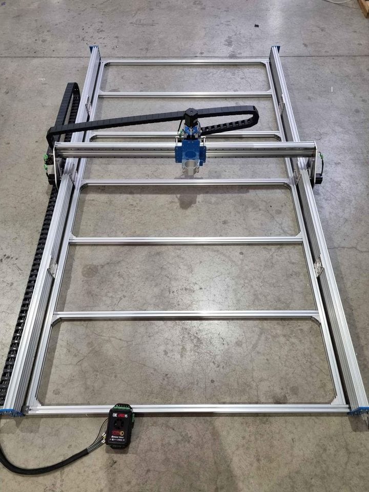
Crate contents
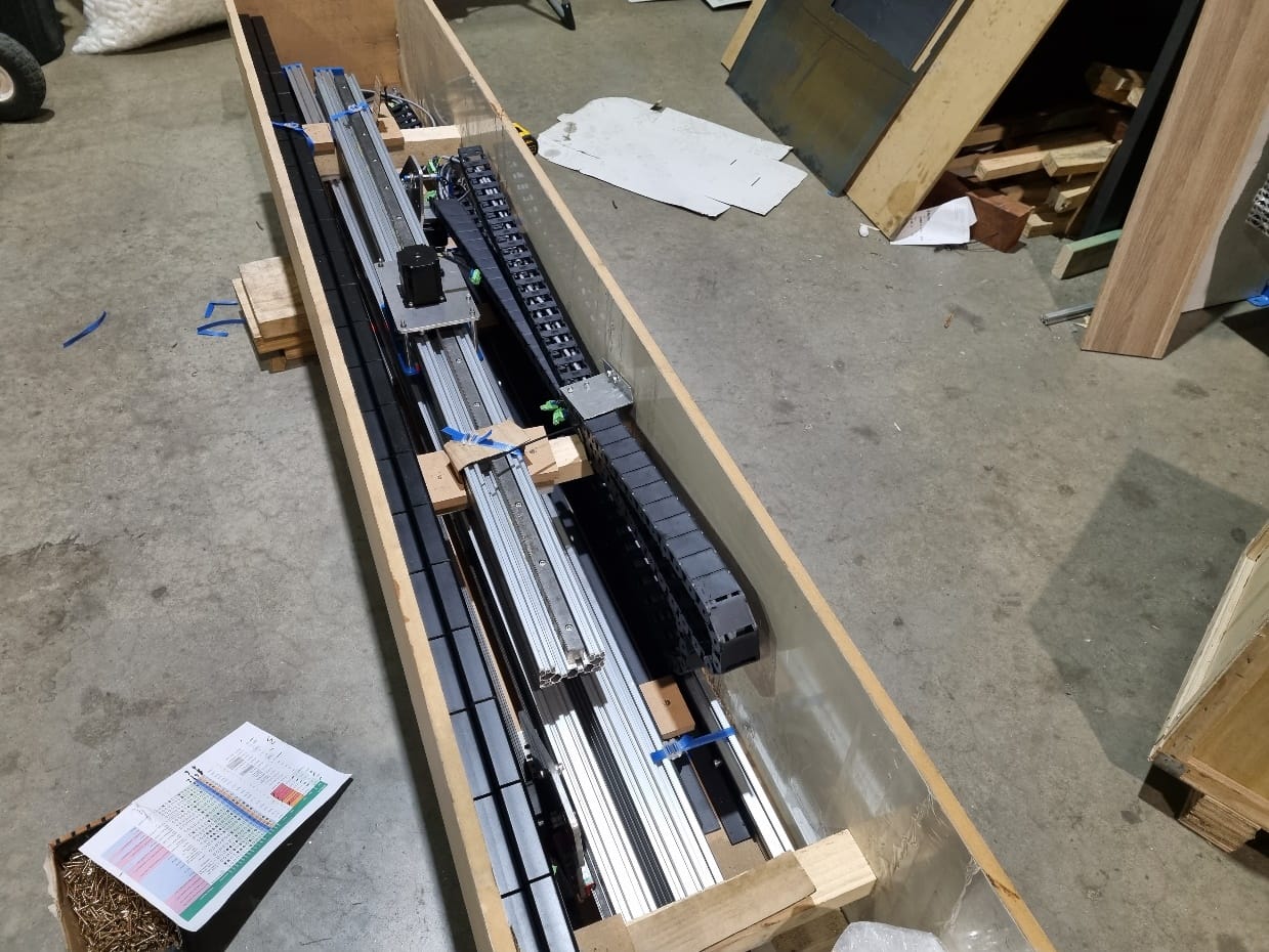
Your Trax arrives in one crate. Inside you will find:
- X axis rail
- 8 × M5 20 mm screws with washers
- YL (left) axis assembly
- YR (right) axis assembly
- Z axis (wrapped in bubble wrap)
- 7 × 30×30 aluminium base lengths
- Drag chain
- CNC controller box (wrapped in bubble wrap)
- USB cable
If you chose upgrade options, you may also have received:
- Spindle and VFD
- Laser module
- T-slots and clamps
We take care packing your CNC, but items are occasionally damaged in transit or missing. If that happens, take photos and get in touch. Missing or damaged items will be replaced.
Tools you will need
- 8 mm spanner
- 4 mm Allen key or hex driver
- Small flat screwdriver
4. Mechanical assembly
- Unpack each component and lay it out on the floor.

The Trax as it arrives in its crate. - Check for damage. If you find any, take photos and email them to Adam.
- Place the two Y axes parallel to each other.
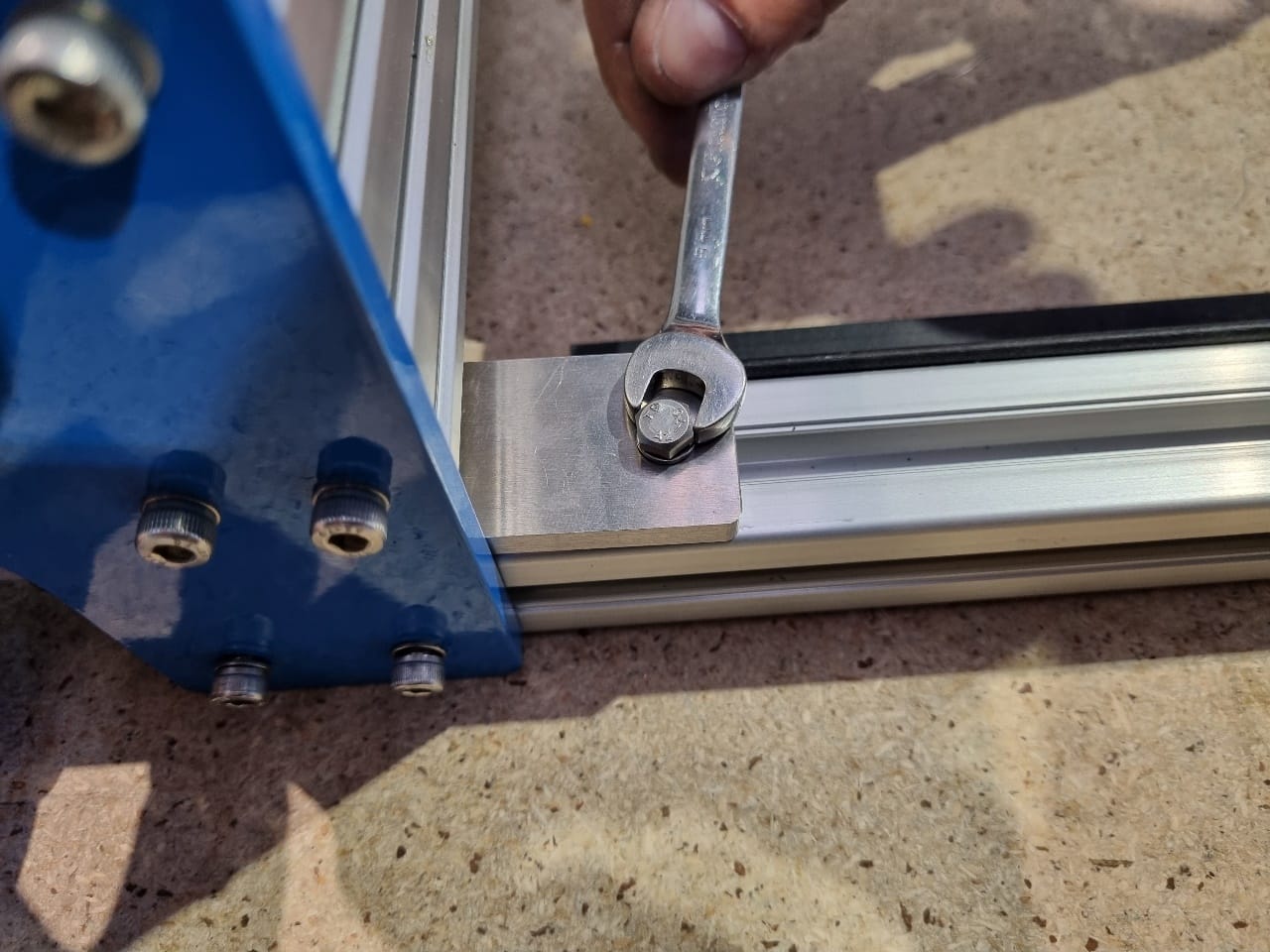
- Attach the front and rear 30×30 rails. Loosen the T-nuts on each side and slide the rail through. Make sure each end is flush with the leg plate.
Make the rail end flush with the leg plate. - Install the remaining base rails.
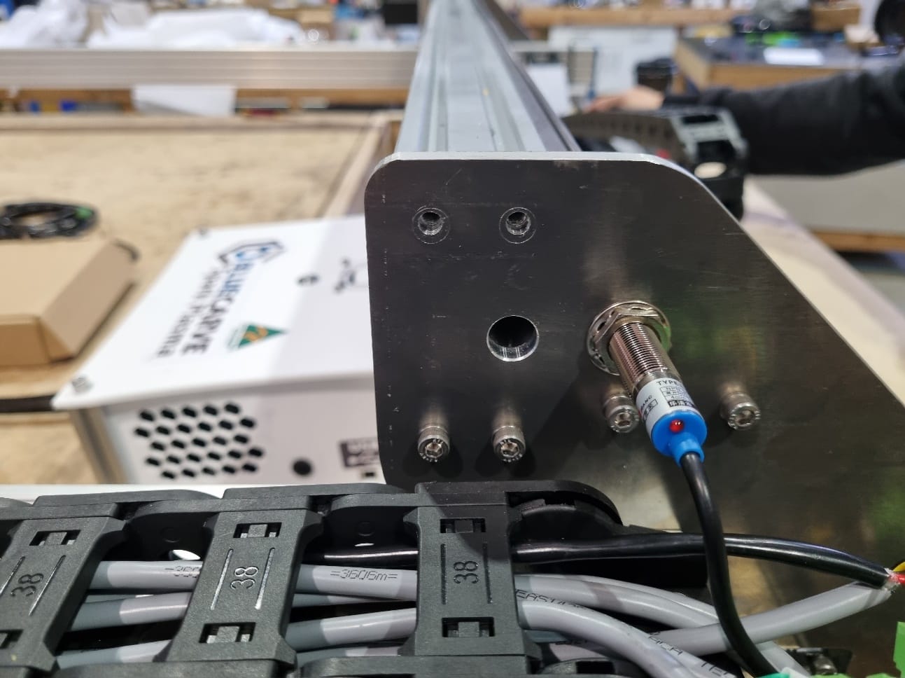
- Attach the X axis rail with its motor facing the back of the CNC and the pivot bolt facing up. Use the 8 × M5x20 bolts, but leave the top 2 bolts out on the YL side for now. They are used later to fit the top drag chain.
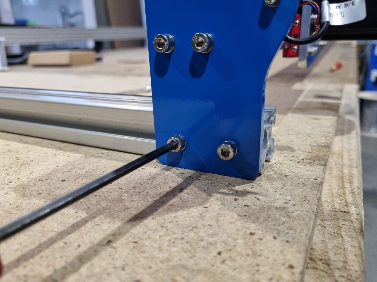
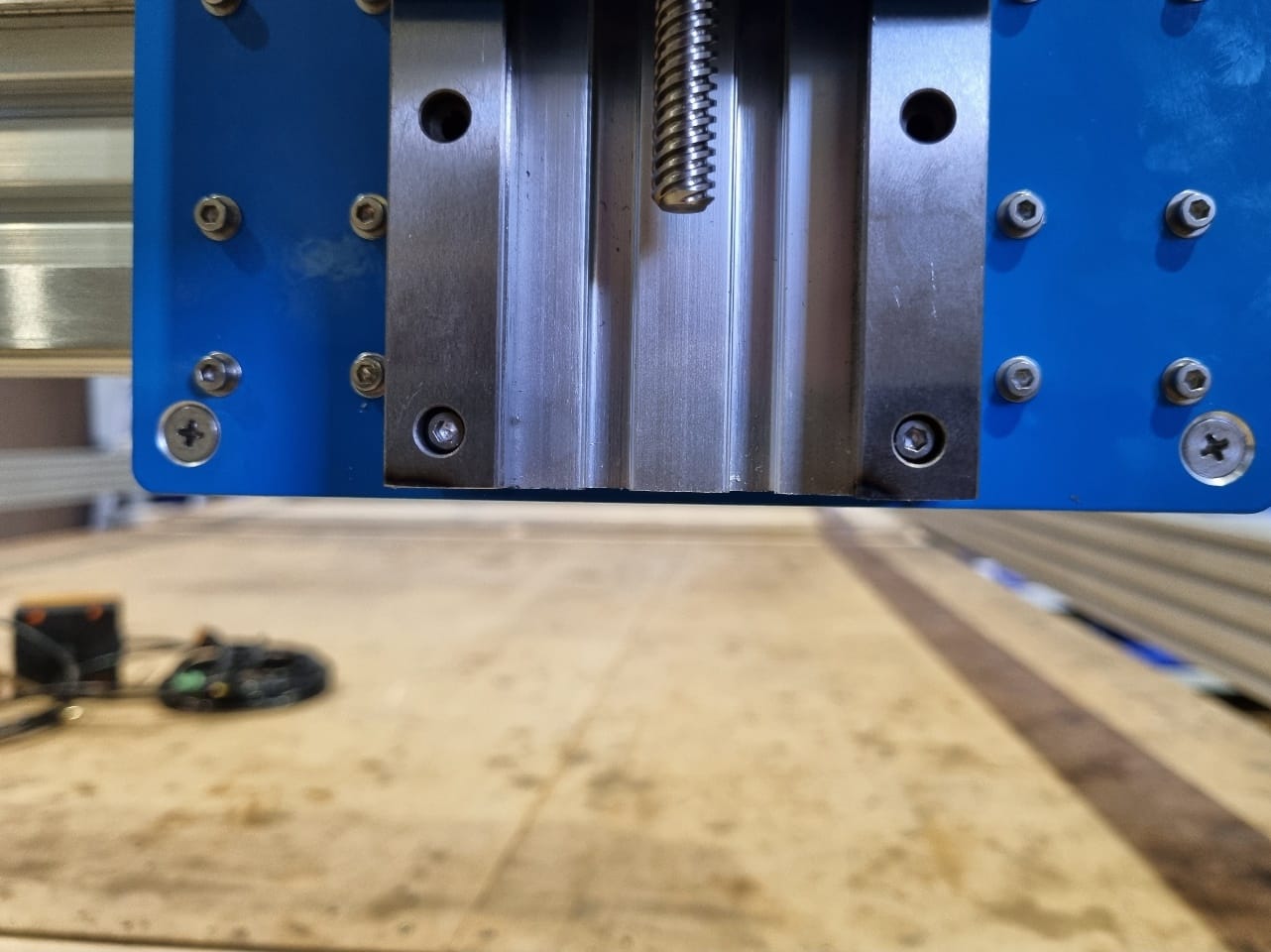
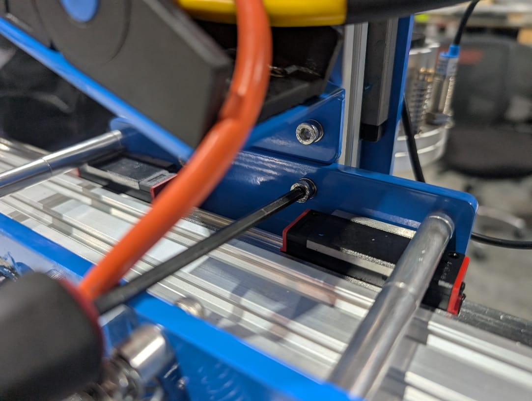
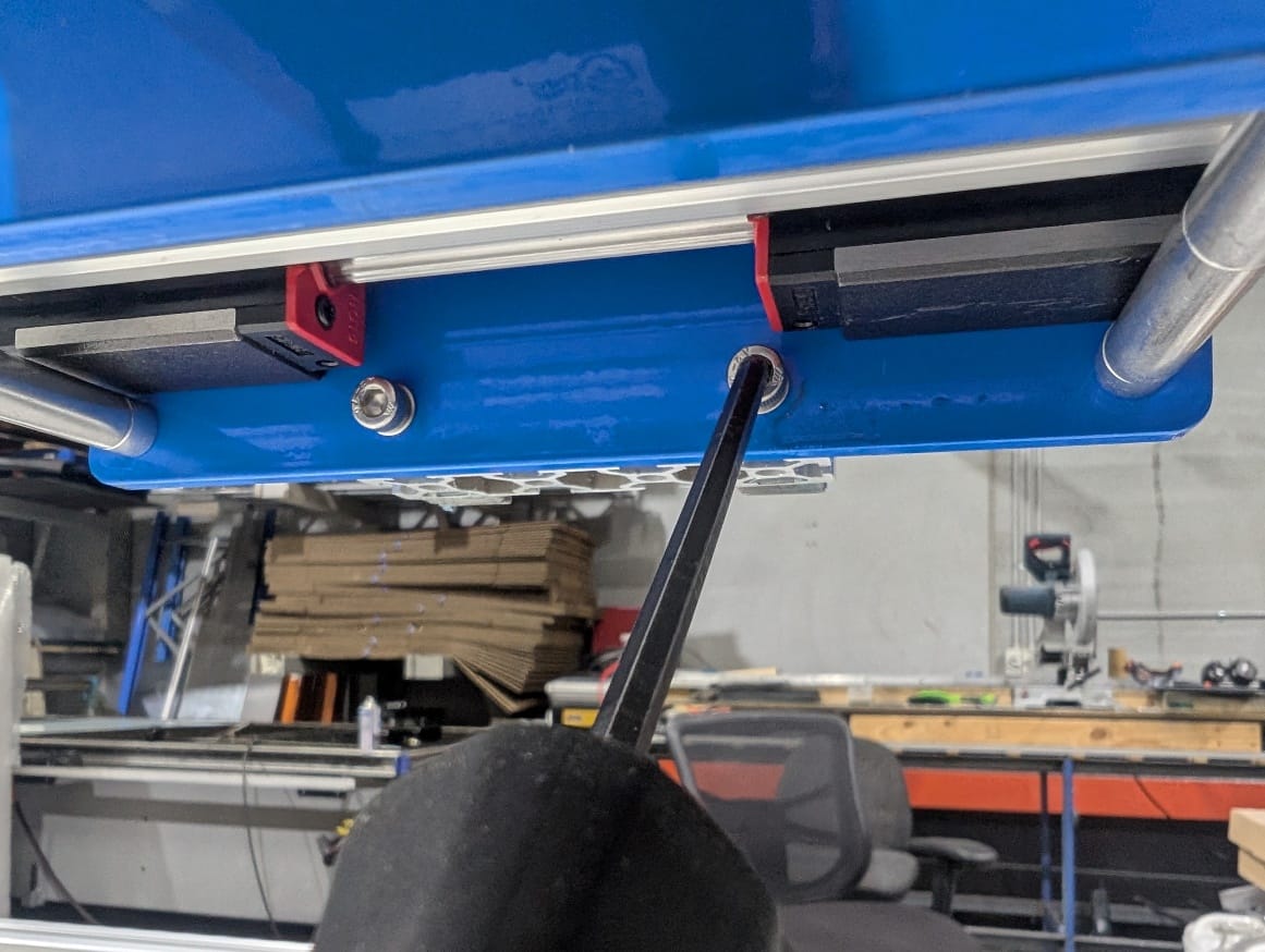
Pivot bolt pointing up. Don’t fit the top two bolts on the YL side yet. - Attach the Z axis to the X axis carriage (standard Z only). Loosen the four bolts on the front plate so you can slide the Z axis down. Make it flush with the bottom plate, then tighten both the top and bottom bolts.
Make the Z axis flush with the bottom plate. Tighten the top bolts. Tighten the bottom bolts. - Attach the drag chain bracket to the front 30×30 rail.
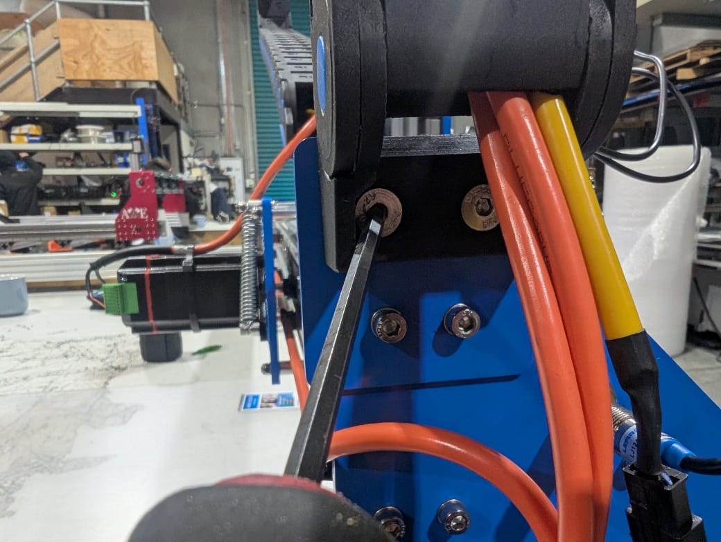
Drag chain bracket on the front rail. - Attach the drag chain to the left-hand (YL) side plate, using the top two holes you left empty in step 6.
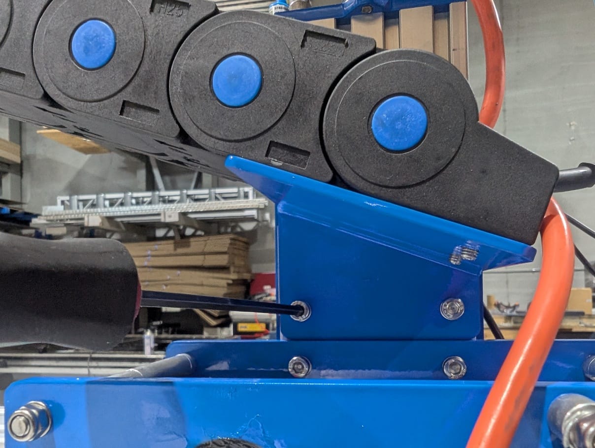
Drag chain on the YL side plate. - Attach the drag chain bracket angle to the back of the Z axis. Loosen the two T-nuts and make sure they turn and engage in the T-slot. Set the drag chain on an angle and tighten.
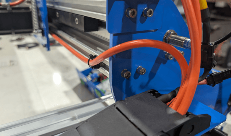
Drag chain bracket angle on the back of the Z axis. - Feed the YR cable through the back of the gantry.
YR cable routed through the back of the gantry.
Installing the Z upgrade
If you ordered your Trax with a Z upgrade, the Z axis arrives uninstalled.
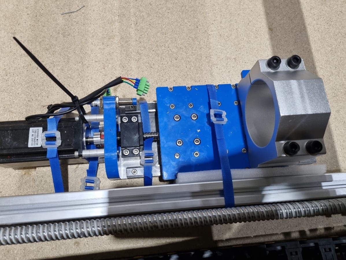
- Attach the Z axis to the X axis carriage using the same four bolts described in step 7.
- Connect the green Z axis motor plug and the Z axis limit switch plug.
- If you have a spindle, plug in the VFD cable. For a water-cooled spindle, also connect the water tubes. It doesn’t matter which tube goes on which of the two water fittings.
Then go back and do steps 8 to 11 above.
5. Table, base board and waste board
Table
Set your CNC up on a solid table. The table’s rigidity decides whether your waste board stays level over time, including through seasonal changes. Humidity and moisture can warp a timber table or waste board. Options include:
- Steel table with a form ply or MDF top
- Timber table with a form ply or MDF top
The Trax comes in two sizes: 1.5×1.5 and 1.5×3. Build a table larger than the machine’s footprint, extending at least 200 mm beyond the CNC’s rail size.
If you add an extra 300 mm to the left of the CNC, you can sit the controller box on the table. If not, mount the controller box on the side of the table or under the top.
Base board
Once the CNC is on the table, install a base board. The most common materials are 18 mm or thicker MDF, or 17 mm form ply. Form ply resists warping over time and is strongly recommended.
| Trax size | Base board size |
|---|---|
| 1.5×1.5 | 1352 × 1495 mm |
| 1.5×3 | 1352 × 2995 mm |
You may need to join 2 sheets to cover a 1.5×1.5, or 3 sheets for a 1.5×3.
Screw the base board directly to the table, sandwiching the aluminium base between the board and the table. Put screws around the edges, missing the aluminium base, and avoid the middle. Screwing into the middle can pull the board down and create a dip. You can still screw down the middle if you support it with 20 mm spacers.
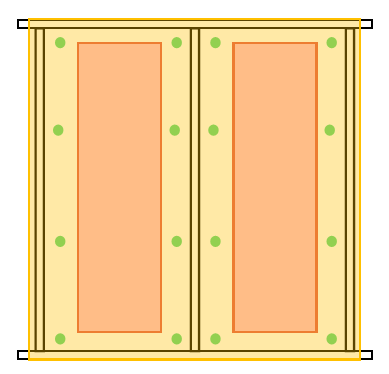
If you bought aluminium rails, install the base board as above. If you bought an aluminium bed, skip this: the bed itself is the base board.
Waste board
The base board fixes the CNC to the table and adds rigidity. The waste board (or sacrificial board) is what you clamp your material to and cut into. It saves you replacing the whole base once it has been carved into and filled with screw holes. Don’t be afraid to cut into it.
For a standard Trax, use 18 mm MDF in the sizes below. These are maximum sizes. A larger board leaves a step between the surfaced area and the rest of the board when you surface it.
| Trax size | Maximum waste board size |
|---|---|
| 1.5×1.5 | 1270 × 1270 mm |
| 1.5×3 | 1270 × 2770 mm |
Line up the bottom left corner of the board directly under the router bit tip at the machine’s bottom left corner. Countersink chipboard screws about halfway into the MDF. Keeping the heads well below the surface stops the bit hitting them and leaves room to surface the board later.
Aluminium rails
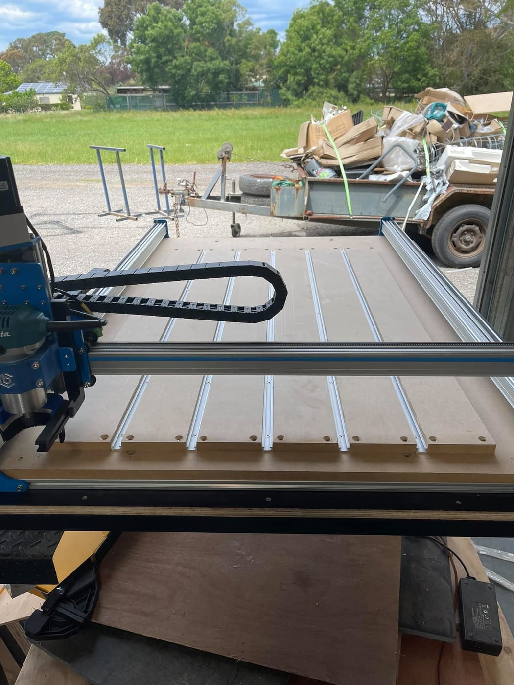
If you bought aluminium rails, follow the rail installation guide by Terry Brown. You still need 18 mm or thicker MDF between the rails. The rail height is 12 mm. Adjust the spacing between rails to suit the number of rails and your CNC size.
6. Electrical connections
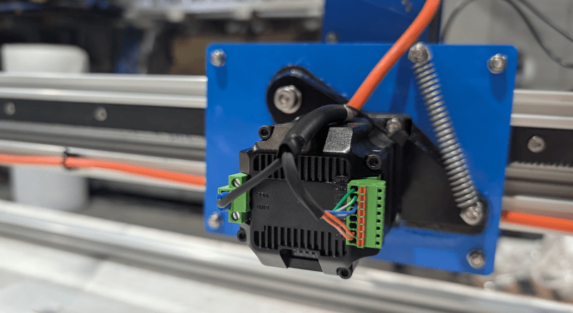
- Connect the motors. Each motor has green plugs. Check there are no loose wires as you connect them.
Motor connection. - Connect the limit switches. Match up the corresponding colours.
Limit switch plugs: match the colours. - Connect the cables to the controller box by matching each cable to its plug.
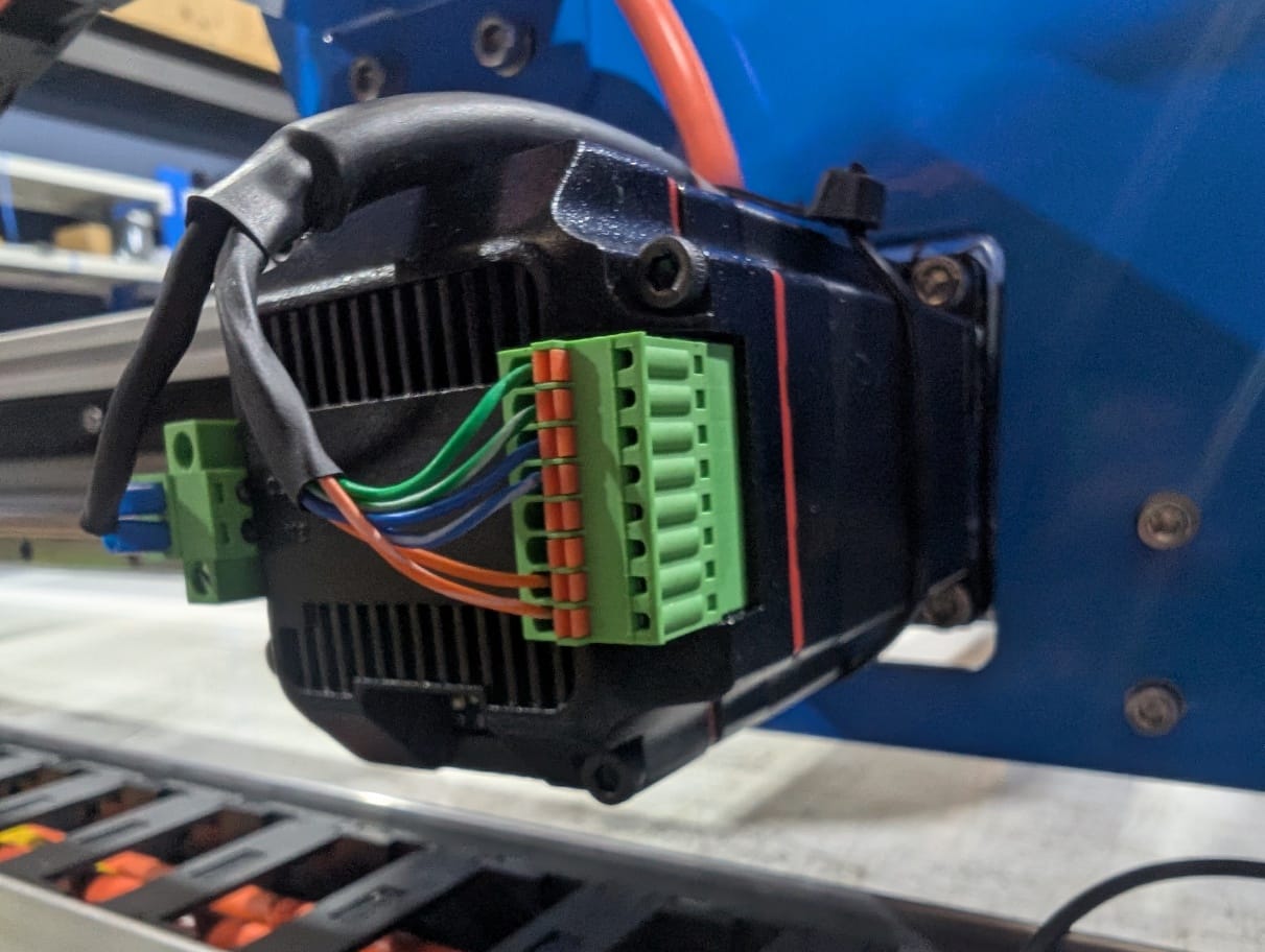
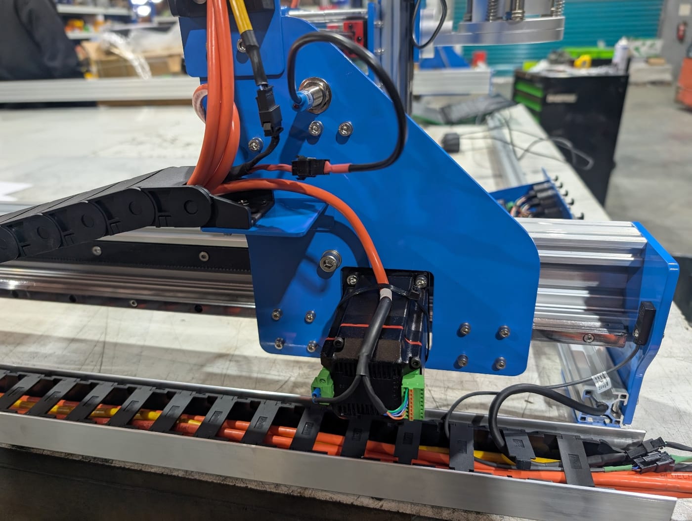
The motor and limit switch cables are keyed, so they can’t be plugged into the wrong socket.
The Trax uses proximity switches as its limit (homing) switches rather than mechanical toggle switches. BlueCarve’s FAQ says they return the machine to 0,0,0 within about 0.05 mm.
What the source states about each connection:
| Connection | Where it goes | Notes |
|---|---|---|
| X, YL, YR motors | Matching cable from the controller | Green plugs on each motor. Check for loose wires. |
| Z motor | Matching cable from the controller | Green plug |
| Limit switches (X, YL, YR, Z) | Matching cable from the controller | Match the colours on each plug. Keyed plugs. |
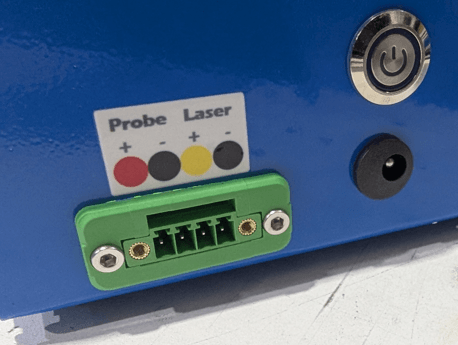
| Z probe | Green 4-pin connector on the controller box, Probe terminals | Red wire to Probe + (P), black wire to Probe − (G) |
| Laser | Green 4-pin connector, Laser terminals | Label shows Laser + (yellow dot) and Laser − (black dot) |
| Computer | USB cable to the controller box | Supplied |
7. Software
Once the mechanical and electrical set-up is done, install the software. Easel is the recommended software for Trax machines with the older GRBL controller. Follow the Easel set-up guide.
For accessories and more information, read on, then return to the software set-up.
8. Accessories
T-slot rail clamps
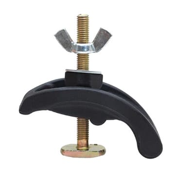
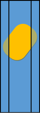
The clamps can go anywhere along the rail. They may look odd when you fit them: you twist the base into the slot so it locks against the rail walls.
Dust boot
Dust boots are available from Adam’s Bits. Owners also share their own boot designs in the BlueCarve owners group on Facebook.
Z probe
A Z probe sets the height of your material just before you start a carve.
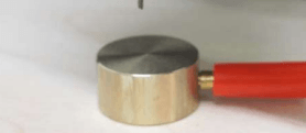
The Z probe is a 15 mm high aluminium puck with a red banana plug lead and a black alligator clip. Connect the red and black wires to the controller box at the socket labelled Probe (older boxes may say PGLG or have coloured labels): red to Probe +, black to Probe −. You set up the probe during the Easel set-up.
9. Laser set-up
The laser comes with a green 4-pin connector that plugs straight into the controller box. If you also have a Z probe, you may need to wire it into the same green 4-pin connector: red wire under P, black wire under G.
Older controllers: the laser positive wire (red or yellow) goes under L, and the black wire always goes under G.
To set up LightBurn and use your laser, follow the BluLaser set-up guide. Read the laser safe operating procedure first.
10. Spindle and VFD set-up
- The e-stop does not stop the spindle. The VFD is not connected to the controller, so stop the spindle at the VFD (STOP/RESET) or its power switch.
- Start the water pump before the spindle. Never run a water-cooled spindle dry.
- Any change to the motor wiring (U/V/W) or the VFD mains wiring must be done by a licensed electrician with the power isolated.
Trax spindles are water cooled. If you bought a spindle, it is one of two:
| Power | Collet | Body diameter | Cooling |
|---|---|---|---|
| 1.5 kW | ER11 | 65 mm | Water cooled |
| 2.2 kW | ER20 | 80 mm | Water cooled |
Water cooling
The spindle comes with a pond pump (limited warranty) and tubing with a barb. If you want a spare pump, choose a submersible pond pump with a flow rate of at least 2500 L/h.
- Connect the pump to the barb on one of the two tubes.
- Put the pump in a reservoir and run the other tube back into the reservoir so the water recirculates. A large lidded tub holding more than 30 litres is suggested.
- Make sure the pump is fully submerged.
VFD
We use a Folinn H1 series variable frequency drive (VFD). You don’t need the manual, but here are the simple manual and the detailed manual.
The spindle and VFD come pre-wired, so you don’t need to touch the wiring.
Spindle direction. The spindle must turn clockwise. If it turns anticlockwise, switch off the VFD and wait until it has fully powered down. A licensed electrician must then swap any two of the U, V and W wires.
For reliability, we don’t connect the VFD to the controller for automatic control. You start and stop the spindle at the VFD.
Operating the VFD
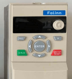
- Start the water pump.
- Turn on the mains power and wait for the VFD to start up.
- Make sure the spindle and router bit are clear of everything.
- Press the green RUN button.
- Adjust the speed by turning the dial.
- The display shows an “F” symbol when it shows speed. Add a zero to read the RPM: 1200 means 12,000 RPM.
- Press STOP/RESET to stop the spindle.
11. Maintenance
Regular maintenance keeps your Trax running for many years. Failing to do reasonable maintenance may void your warranty.
- Keep the linear rails and rack clean and free of dust and obstructions.
- Lubricate the linear rails and the rack and pinion.
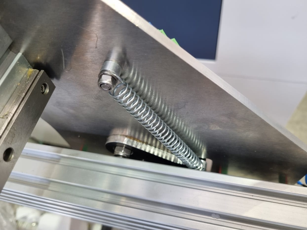
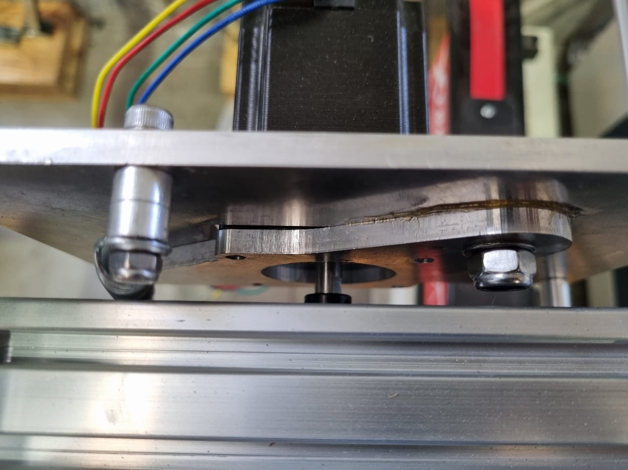
- Check the motor hinges. They should move freely up and down, but not side to side. Inspect and remove any slop from the spring and motor arm. The hinge bolt may need adjusting over time.
| Part | Lubricant |
|---|---|
| Linear rails | White lithium grease spray |
| Rack and pinion | Multi-purpose lithium grease |
12. Troubleshooting
| Problem | Check |
|---|---|
| All motors stop at once during a job | The closed-loop motors go into “motor fault” and turn the other motors off after a critical failure, such as the gantry hitting an end. Find and clear the cause, then reset the fault by turning the controller off and on again. |
| USB connection drops or behaves erratically | If the CNC sits directly on a steel table, fit a timber top to separate it from the steel. Try another USB port (avoid the blue USB 3.0 port) and another computer. |
| Easel’s Carve button doesn’t turn green | Check the driver is installed, try another USB port and another computer. See the Easel set-up guide. |
| A limit switch doesn’t activate during set-up | Check the switch plug is connected and the colours match. |
| Machine homes in the wrong direction (GRBL controller) | In Easel’s Machine Inspector (Ctrl+Shift+D), check $23=3 (home is Z up, X left, Y front) and $22=1 (homing enabled). |
| Z probe retracts before the bit touches the plate | You may have a machine grounding issue. Email Adam about grounding your machine. |
| Spindle turns anticlockwise | Power down the VFD fully. A licensed electrician must swap two of the U/V/W wires. |
| Spindle keeps running after pressing the e-stop | This is expected: the VFD isn’t connected to the controller. Stop it with STOP/RESET on the VFD or its power switch. |
| Slop, chatter or poor accuracy | Check the motor hinges move up and down but not side to side; adjust the hinge bolt. Clean and lubricate the rails and rack. |
| Dip in the middle of the base board | Screws in the middle can pull the board down. Remove them, or support the middle with 20 mm spacers. |
| Controller overheating | Keep the controller in the open with free-flowing air. |
Email adam@bluecarve.com.au with your machine model, size and a photo or short video of the problem. Owners also help each other in the BlueCarve owners group on Facebook.
Stuck on something? I’m Bingo. Answer a couple of questions and I’ll point you to the fix.