
Spark Plasma CNC Set Up
Spark Plasma CNC Set Up
| Version | Motor connections |
|---|---|
| Open loop | Green connectors on each motor |
| Closed loop | Every motor connection is keyed by colour and plug type |
Everything else is the same on both: the table, and the MyPlasm CNC set-up. For MyPlasm you only need to pick the config for your rack: straight or helical (see MyPlasm CNC software set-up).
1. Safety
A CNC plasma cutter is safe to run when you follow the precautions below. Read the full Plasma Safe Operating Procedure before your first cut.
- Never leave the CNC unattended.
- Protect your eyes from the plasma arc. Ordinary safety glasses are not enough: wear a welding helmet or face shield with a welding shade lens. As a guide, use shade 5 up to 40 A, shade 6 for 40–60 A and shade 8 for 60–80 A, and confirm the shade in your plasma cutter’s manual.
- Keep your body a safe distance from the CNC.
- Keep air flowing freely around the CNC controller.
- Take care when handling material before and after cutting. Cut parts and dross stay hot.
- Make sure anyone nearby also wears eye protection with a suitable welding shade lens while the CNC is running.
- Restrict access to the room where the CNC is running.
- Only connect power to the plasma cutter once the torch is fixed to the Z axis, pointing straight down.
- Follow any extra safety requirements from your plasma cutter’s supplier.
2. Warranty
Our goods come with guarantees that cannot be excluded under the Australian Consumer Law. You are entitled to a replacement or refund for a major failure and compensation for any other reasonably foreseeable loss or damage. You are also entitled to have the goods repaired or replaced if the goods fail to be of acceptable quality and the failure does not amount to a major failure.
Operation and care
We want you to be happy with your new BlueCarve Spark Plasma CNC. Please read this set-up guide and follow the recommended procedures. If you have any questions about keeping your machine in good working condition, contact BlueCarve CNC.
Plasma units supplied by BlueCarve CNC are supported within the warranty period. After the BlueCarve CNC warranty period ends, the plasma unit is covered by its supplier for the rest of the supplier’s warranty period, counted from the date of shipping or pick-up.
Warranty period
The warranty starts when your Spark Plasma CNC ships from our facility or is picked up, and runs for 12 months. It covers repairs to correct defects in materials or workmanship that existed at the time of collection or shipping. All requests must be approved by BlueCarve CNC before any work is done. Specific exceptions are listed under Exclusions. BlueCarve CNC will supply parts during the warranty period in line with the Terms, Limitations and Conditions below.
Limit of warranty
This warranty is only provided in Australia and to the original purchaser. By accepting the quote sent by BlueCarve CNC, you agreed to help BlueCarve CNC diagnose and repair your machine. Once the issue and fix are identified, BlueCarve CNC may send you the replacement part at our cost. Where a component has to be sent back to the manufacturer, BlueCarve CNC does not cover postage. BlueCarve CNC does not have technicians for on-site work, but you are welcome to bring your machine or components in and we will complete the repair free of charge during the warranty period.
Exclusions
Components subject to normal wear during the warranty period, such as plasma unit consumables, are not covered.
Damage caused by handling, misuse, or corrosion from exposure to materials voids the warranty.
Component failure caused by misuse or abuse of the machine (for example changing recommended settings, exceeding the plasma cutter’s stated duty cycle, or using incompatible materials) voids the warranty.
Terms, limitations and conditions
Maintenance. All machines need periodic maintenance as outlined in this guide, and it is the customer’s responsibility to do it. Failing to maintain the machine may void the warranty.
Damage from accident, misuse or alteration. Damage or failure caused by an object striking the machine, fire, theft, freezing, environmental exposure, exceeding the duty cycle, modifying or altering the machine, or any other misuse is not covered. Damage or failure due to natural disasters (flood, tropical cyclone and so on) or acts of war is not covered.
Labour. BlueCarve CNC will not reimburse unauthorised labour used for warranty repairs, except in special circumstances, which are handled case by case at BlueCarve CNC’s discretion.
Product advice. Suggestions about how to use products are not warranties. The customer is responsible for deciding whether products are suitable and how to use them.
Other terms. BlueCarve CNC does not authorise any person to create any other obligation or liability in connection with this machine. Report any shipping damage to both the freight carrier and BlueCarve CNC as soon as possible.
3. Workflow
- Unpack your CNC and check for damage.
- Assemble the CNC using the steps in this guide.
- If you bought legs and a water tray, follow the Spark Plasma legs and water tray guide.
- Install MyPlasm CNC and load the BlueCarve configuration.
- Start cutting.
4. What’s in the box
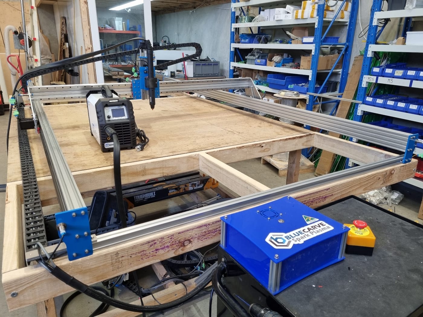
Your order arrives in one or two boxes. Inside you will find:
- X axis rail
- 8 x M5 x 20mm screws with washers
- YL axis (left side) assembly
- YR axis (right side) assembly
- Z axis (wrapped in bubble wrap)
- 2 x 30×30 aluminium rails (front and rear, interchangeable)
- Drag chain
- CNC controller box (wrapped in bubble wrap)
- USB cable
- 24V power supply
- Signal cable from the CNC controller to the plasma cutter
If you chose upgrades, you may also have received:
- Plasma cutter (Thermacut)
- Table and legs
- Water trays
- Basic knife bed
- Plasma protector fluid
Tools you will need
- 8mm spanner
- 4mm Allen key or hex driver
- Small flat screwdriver
5. Mechanical assembly
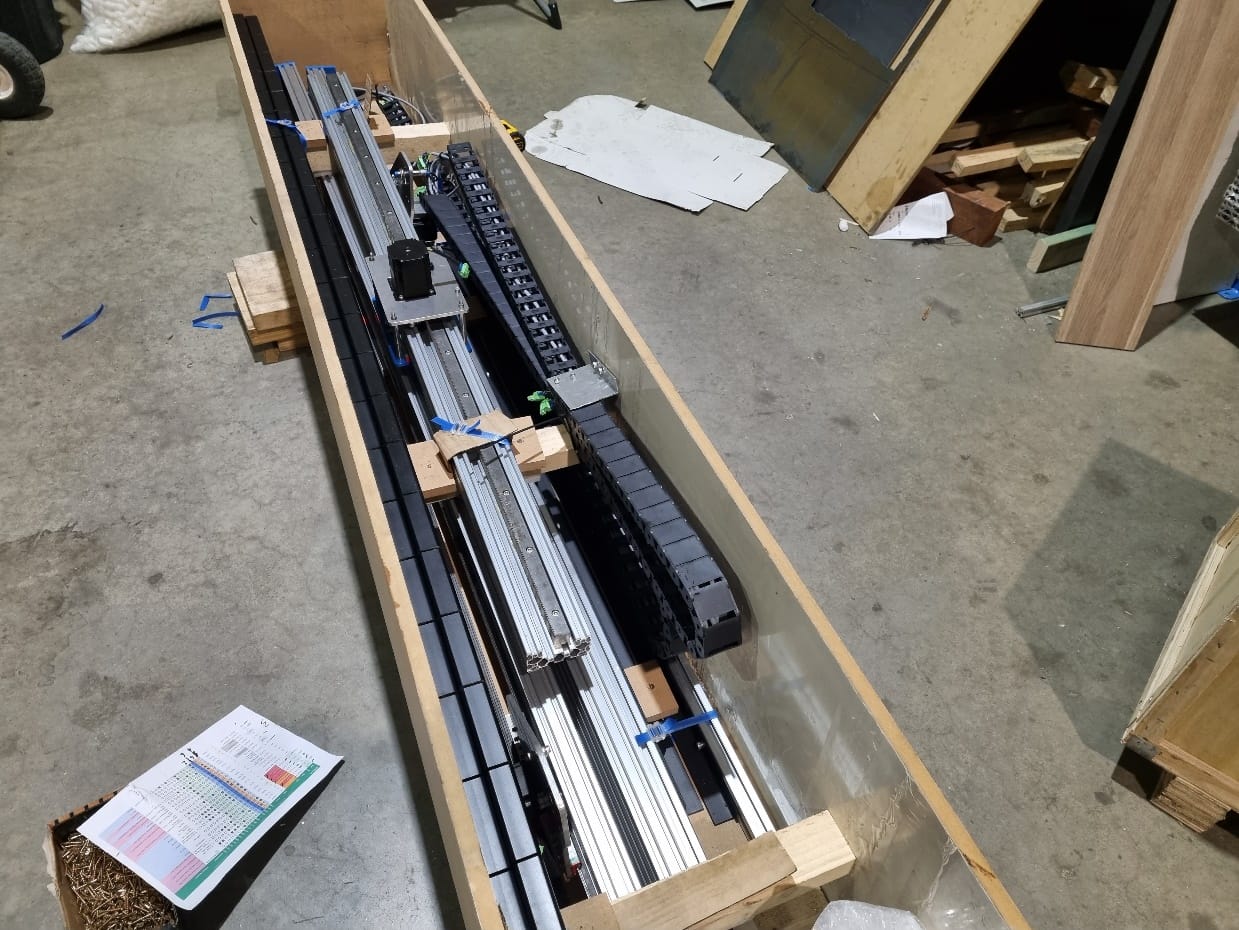
- Unpack each component and lay it out on the floor.

Components as they arrive in the crate. - Check every part for damage. If you spot any, take photos and email them to Adam.
- Place both Y axes parallel to each other.
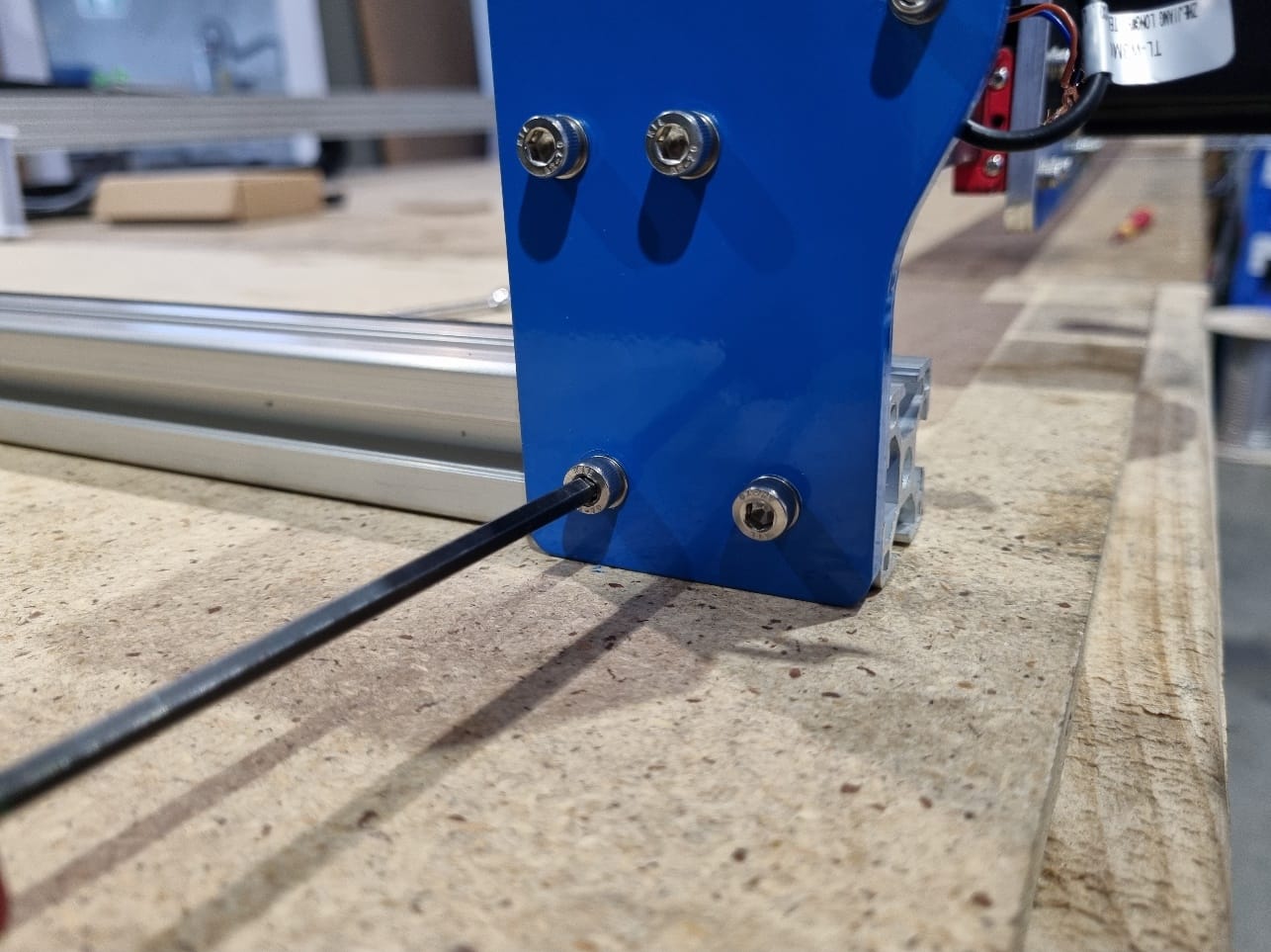
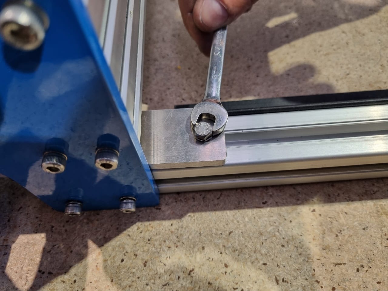
- Attach the front and rear 30×30 rails. Loosen the T nuts on each side and slide the rail through. Make each end flush with the leg plate.
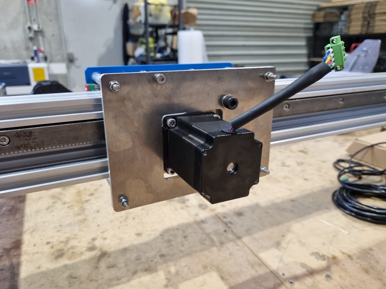
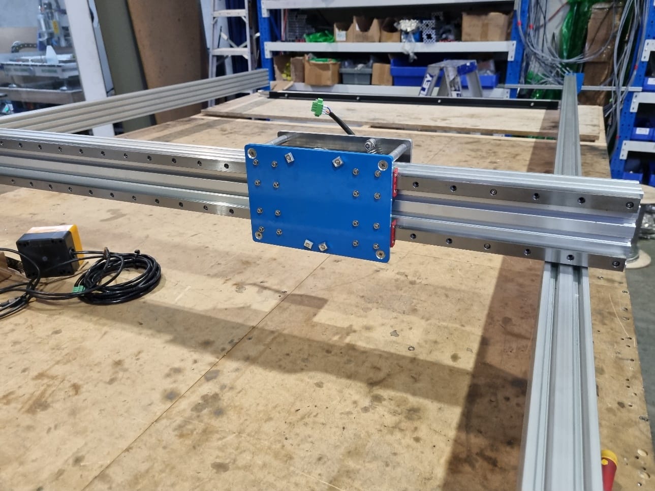
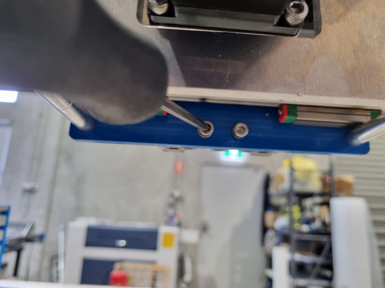
Make the rail flush with the end plate, then tighten. - Attach the X axis rail with the blue plate facing forward and the motor cable pointing up. Use the 8 x M5 x 20mm bolts, 4 on each side, but leave the top 2 bolts out on the YL (left) side. These holes are used later for the drag chain.
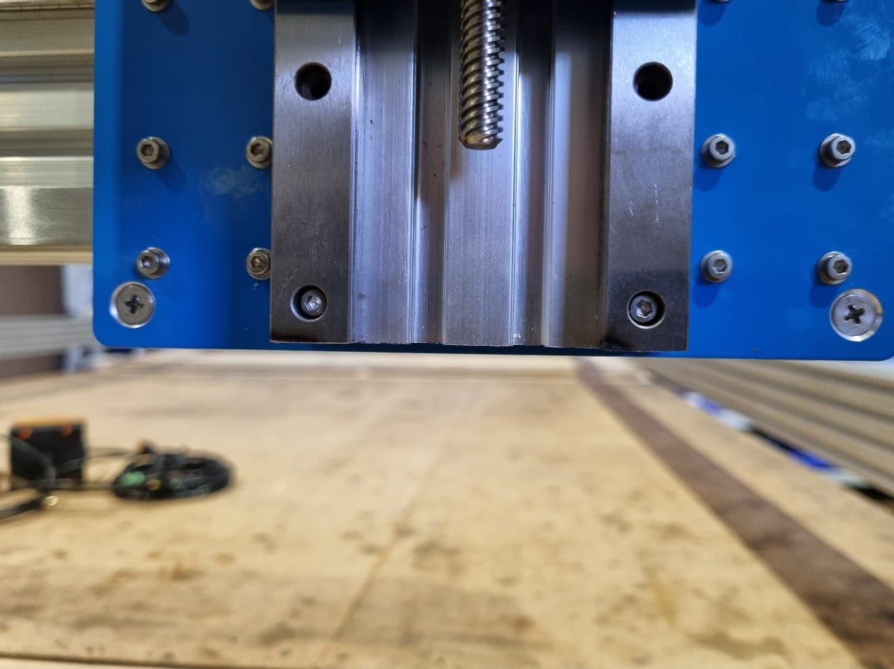
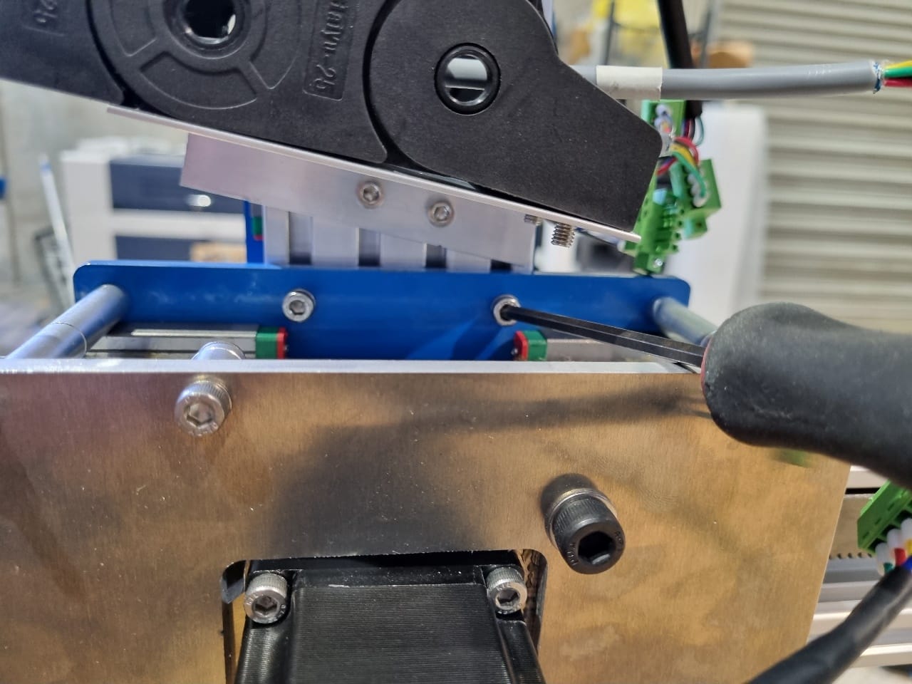
Motor cable pointing up. Blue plate facing forward. YL side: the top 2 holes are left free for the drag chain. - Attach the Z axis to the X axis carriage. Loosen the 4 bolts on the front plate so you can slide the Z axis down. Make it flush with the bottom plate, then tighten both the top and bottom bolts.
Make the Z axis flush with the bottom plate. Tighten the top bolts. Tighten the bottom bolts. - Attach the drag chain bracket to the front 30×30 rail.
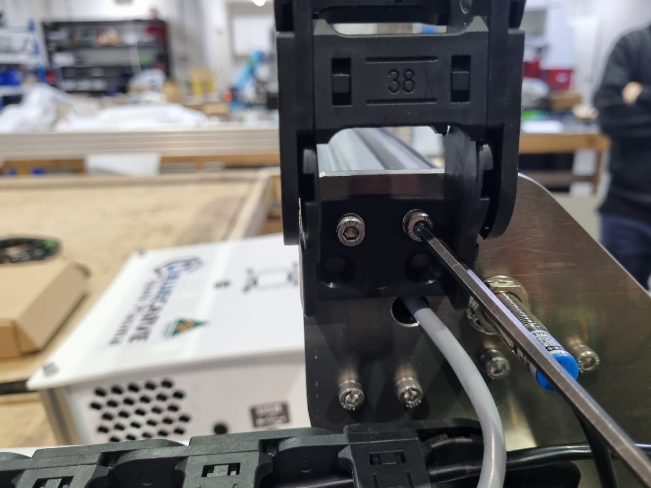
Drag chain bracket on the front rail. - Attach the drag chain to the left-hand (YL) side plate.
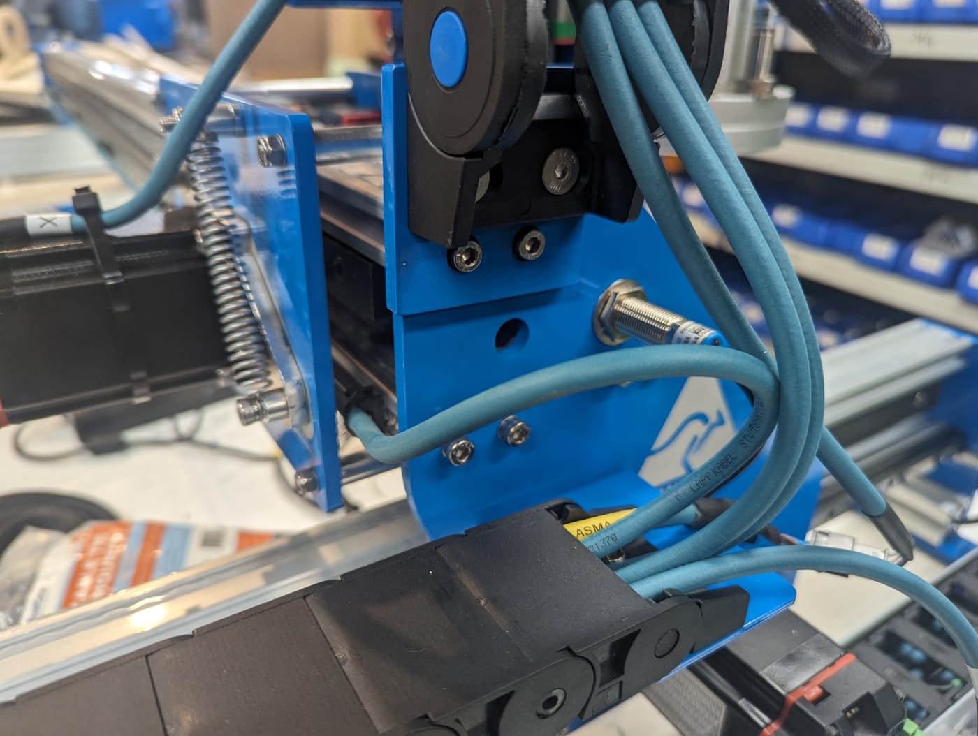
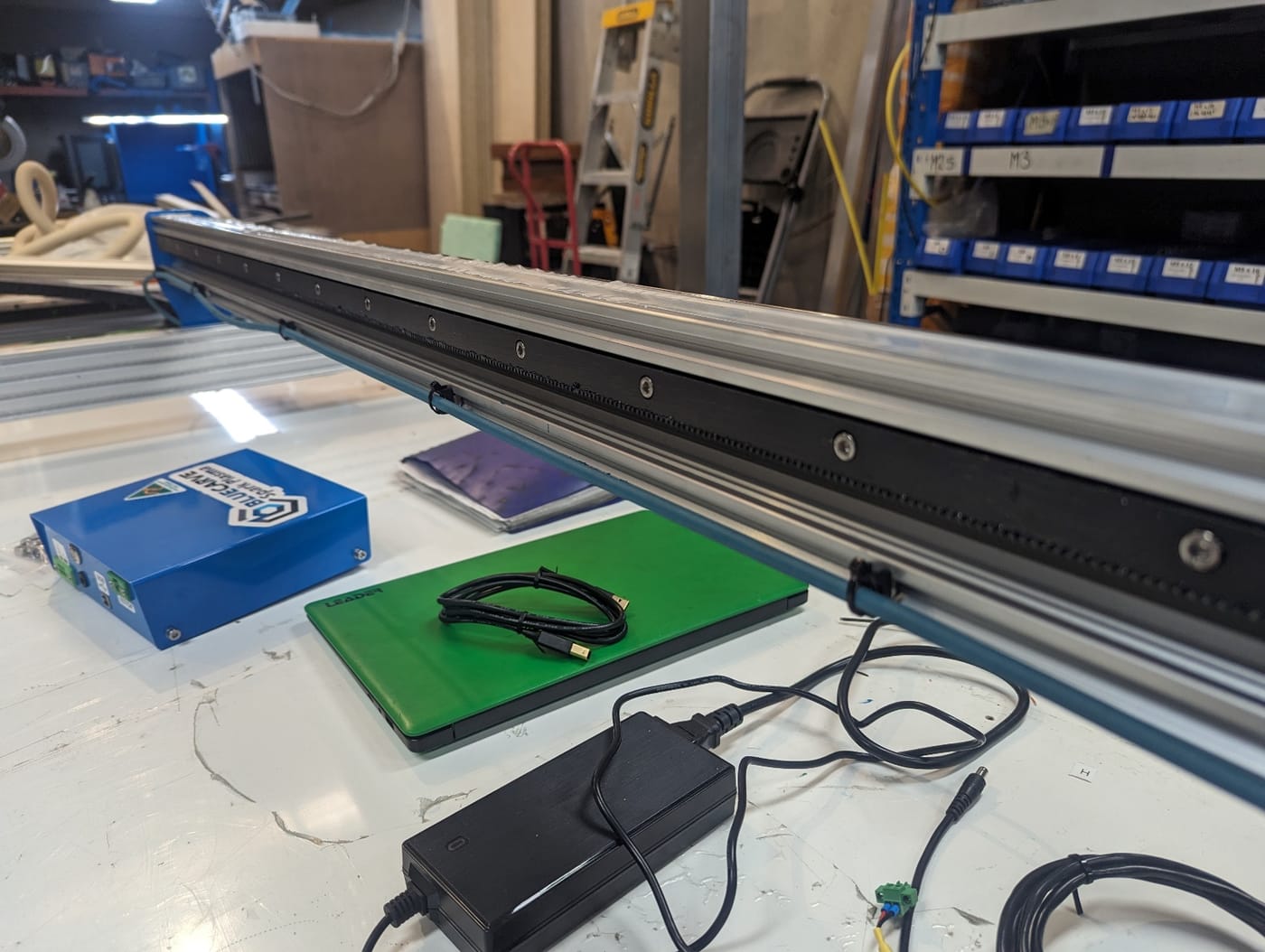
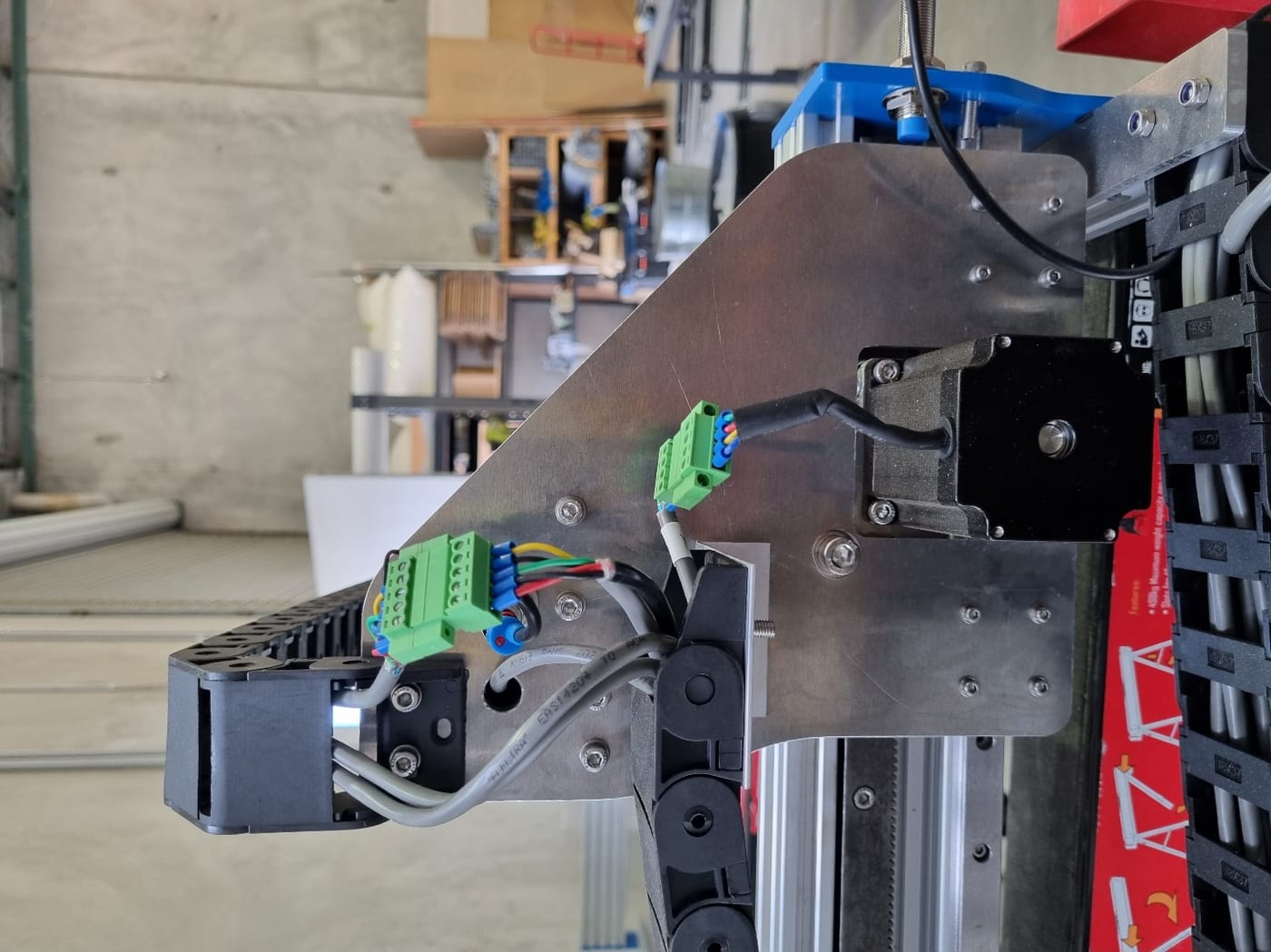
Drag chain fixed to the YL side plate. - Feed the X, Z and H cables through the drag chain. The H cable carries limit switch power and signals to all axes.
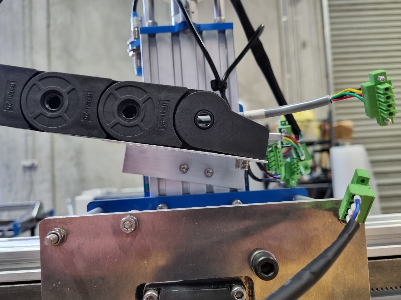
- Attach the drag chain bracket angle to the back of the Z axis. Loosen the two T nuts and make sure they turn and engage in the T slot. Angle the drag chain to the side, then tighten.
Angle the drag chain to the side. - Feed the YR cable through the hole in the side plate to the right-hand side.
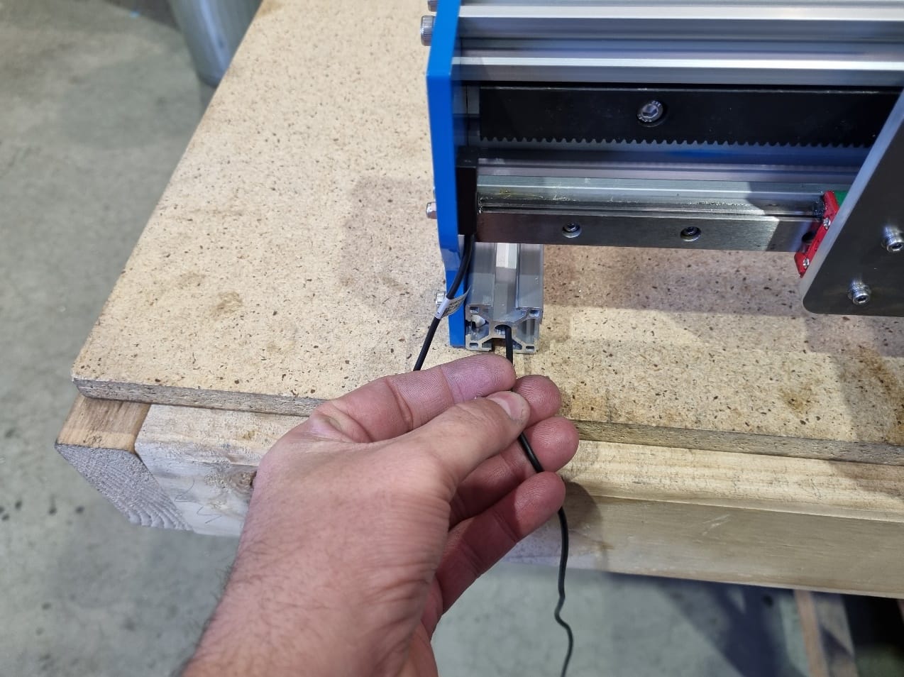
YR cable running to the right-hand side. - Feed the right-hand Y limit switch cable through the hollow centre of the 30×30 rail to the left-hand side.
Limit switch cable through the rail.
6. Electrical connections
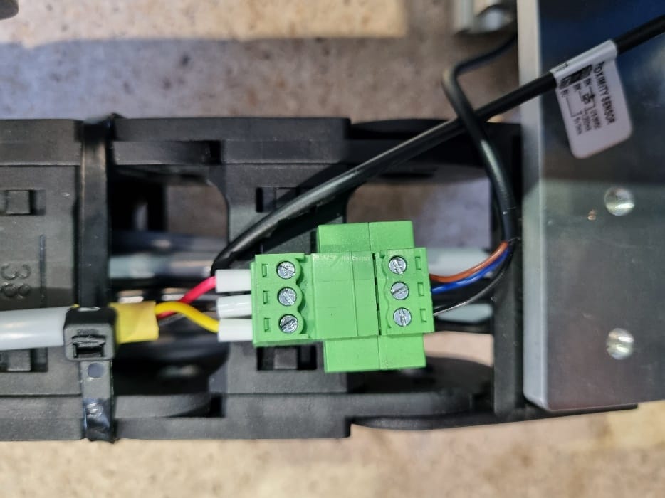
- Connect the YR limit switch at the drag chain junction.
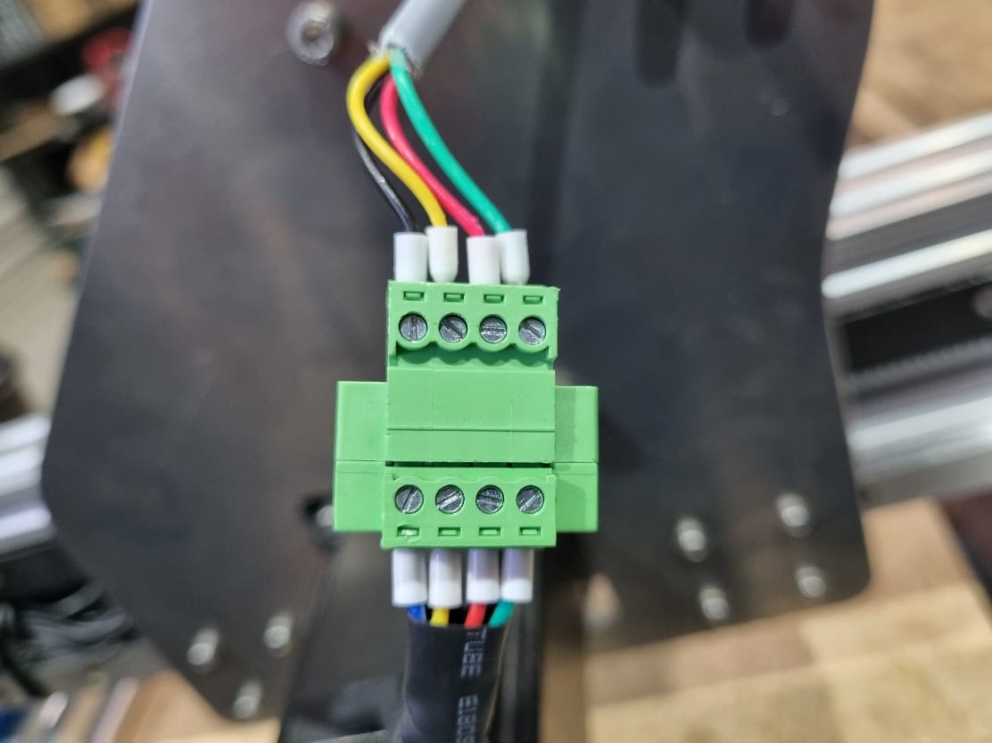
YR limit switch connection at the drag chain. Limit switch wire Brown Blue Black Cable wire Red Black Yellow - Connect the YR motor.
YR motor connection. Motor cable Black Yellow Red Green Extension cable Blue Yellow Red Green - Connect the YL motor (4-pin plug) and YL limit switch (5-pin plug).
YL: 5-pin limit switch plug and 4-pin motor plug. - Connect the X motor, Z motor and H cable. Each plug pair is marked with its letter.
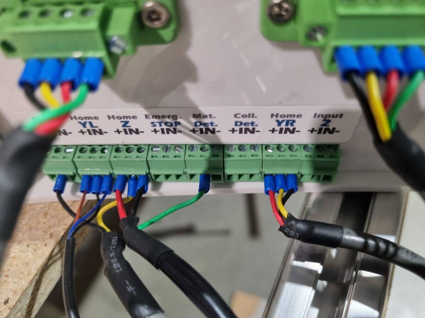
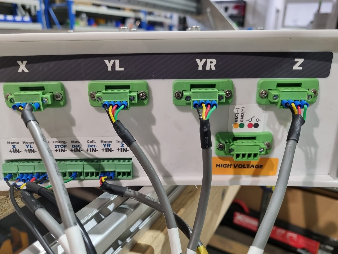
X Z H - Connect the cables to the controller box. The motor plugs are labelled X, YL, YR and Z, and the limit switches go to the matching Home inputs.
Controller input terminals. Motor connections and the plasma cutter connection (labelled High Voltage). The plasma cutter connection is set to 50:1 by default. - Connect the USB cable and the 24V power supply.
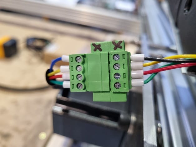
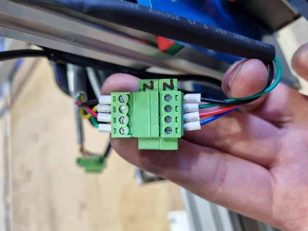
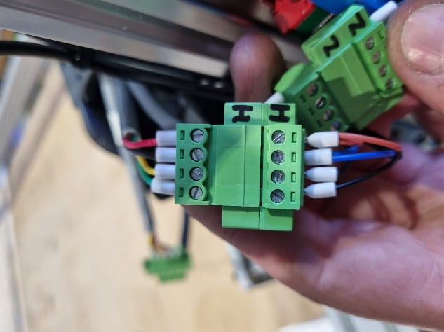
7. Knife bed
- Older machines only: if black angles are fitted to the front and rear rails, remove them.
- Slot the knives into the knife supports. Each machine size uses a different number of knives.
If you have the water tray, the knife slots and knives are covered in the Spark Plasma legs and water tray guide.
8. Plasma cutter and air supply
BlueCarve supplies Thermacut plasma cutters for the Spark Plasma (the first-cut video below uses a Thermacut 40SD). Older machines may have an SWS Speedcut 50, which connects to the CNC the same way. If you bought a plasma cutter, it arrives separately from the CNC. Inside you will find:
- Plasma cutter
- Machine (vertical) torch
- Consumables
- Ground cable
- Plasma connection (signal) cable
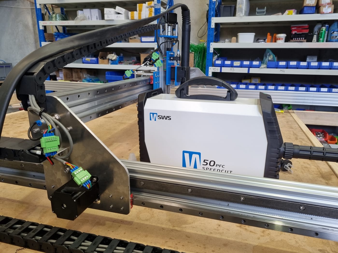
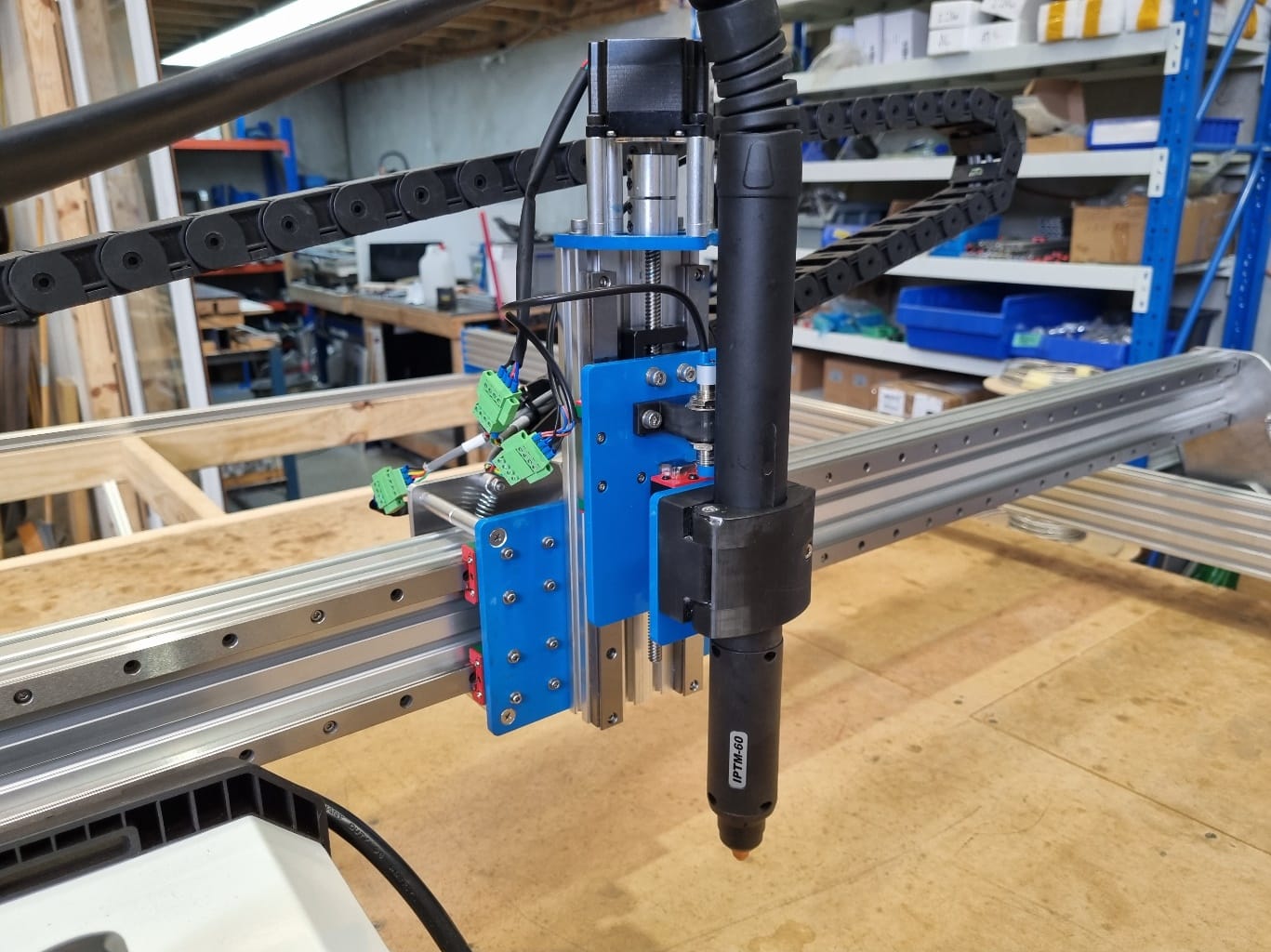
- Mount the torch in the Z axis torch holder, pointing straight down.
Torch mounted vertically on the Z axis. - Run the torch cable along the gantry. It is fine to feed it through the drag chain.
- Connect the signal cable between the CNC controller and the plasma cutter.
- Connect the ground cable as described in your plasma cutter’s manual.
- Connect the air supply (see below).
- Only now plug in the plasma cutter’s power.
Air supply
- You need a compressor that supplies at least 100 litres per minute at 60psi.
- Use an air filter, such as an AT1000, to keep moisture and oil out of the plasma cutter.
- Follow your plasma cutter manufacturer’s recommendations for the air supply, including the filter, water trap, regulator and pressure.
9. MyPlasm CNC software set-up
Choose the right configuration
The configuration file depends on the type of gear rack on your machine.
| Your machine | Rack | Gear ratio | Configuration file |
|---|---|---|---|
| Bought before February 2026, and all landscape (1.5×1.0) machines | Straight | 50.25 | Download straight-rack config |
| Bought after February 2026 (except landscape) | Helical | 66.7 | Download helical-rack config |
If you’re not sure which rack you have, email Adam before loading a configuration.
Install and configure
- Download and install MyPlasm CNC from myplasmcnc.com.pl.
Windows 11 driver problemOn Windows 11 the driver can fail to install. If it does, open Windows Security > Device security > Core isolation, turn off Memory integrity, restart the computer, then reinstall MyPlasm CNC.
- Download the configuration file for your rack type (table above). Don’t unzip it: MyPlasm CNC loads the .zip file directly.
- Open MyPlasm CNC and click the cog (top right).
- Go to the Software tab and click Load Configuration. Select the .zip configuration file you downloaded and click Open.
- Go to the Machine tab and set the Axis Soft Limits for your machine size:
Machine size X Y Z 1.5×1.0 (landscape) 1270 770 150 1.5×1.5 1270 1270 150 1.5×3.0 1270 2770 150 1.8×3.3 1570 3070 150
10. Your first cut
Watch the BlueCarve Spark Plasma CNC first cut guide (filmed with a Thermacut 40SD). It walks through a first cut from start to finish.
For more detail on the software, see the MyPlasm manuals:
11. Maintenance
Regular maintenance keeps your Spark Plasma running for many years. Failing to do reasonable maintenance may void your warranty.
- Keep the linear rails and rack clean and free of dust and obstructions.
- Keep the linear rails and the rack and pinions lubricated:
- Rack: multi-purpose lithium grease.
- Linear rails: white lithium grease spray.
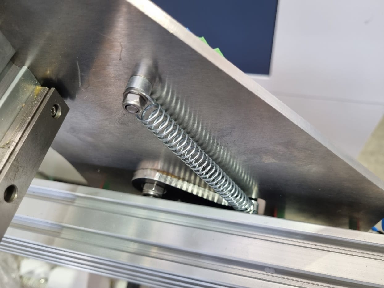
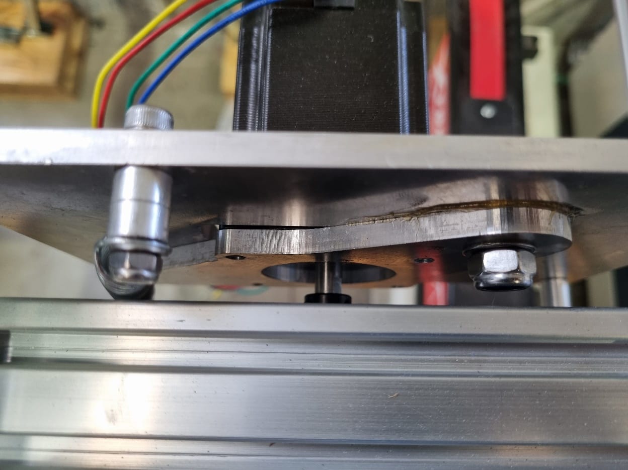
- Check that each motor hinge moves freely up and down but not left and right. The hinge bolt may need adjusting over time.
12. Troubleshooting
| Problem | Check |
|---|---|
| MyPlasm CNC driver won’t install on Windows 11 | Turn off Core isolation (Memory integrity), restart and reinstall. See MyPlasm CNC software set-up. |
| Cut parts come out the wrong size, or the machine travels the wrong distance | Check you loaded the right configuration for your rack: straight rack (50.25) for machines bought before February 2026 and landscape machines, helical rack (66.7) for machines bought after. |
| Machine stops short of the edge, or tries to run past it | Check the Axis Soft Limits on the Machine tab match your machine size. |
| A motor doesn’t move or one side of the gantry lags | Check that motor’s plug is fully seated and wired to the colours in Electrical connections, and that the plug is in the right socket on the controller. |
| Y axis won’t home or homes on one side only | Check the YR limit switch connection at the drag chain junction and the YL 5-pin limit switch plug. |
| Rough or noisy movement | Clean and lubricate the rack and linear rails. Check the motor hinges move up and down freely and adjust the hinge bolt if needed. |
| Poor cut quality | Check your cut values against the plasma cutter’s cut chart, check the consumables, and check the air supply meets 100 L/min at 60psi and your plasma cutter manufacturer’s filter, water trap, regulator and pressure recommendations. |
For more problems and fixes, see the full Spark Plasma troubleshooting page.
Email adam@bluecarve.com.au with your machine model, size and a photo or short video of the problem. Owners also help each other in the BlueCarve owners group on Facebook.
Stuck on something? I’m Bingo. Answer a couple of questions and I’ll point you to the fix.